In this article I describe my newest project, a terrarium controller that is based on Node Red (the “brain”) and an ESP32 (the “brute”).
As the STEM Education Summit came closer to completion, I starter work on a new project that combined an ESP32 with Node Red running on a Raspberry Pi to create a controller for a simple terrarium.
Inspiration
I was inspired by my son Ari, who started putting plants in jars a couple of years ago.
Ari planted small succulents in ex-kitchen jars, tested the humidity of the soil with his finger, and added a few drops of water when he thought the soil was too dry. Ari also placed the jars near a window so the succulents could get some light.
One day, Ari found a small plant “incubator” machine. Something like this (not the actual device that Ari used).
When I saw it, I though that this would be a perfect topic for a project that would engage him, as well as give me the opportunity to address my project-based learning deficit of the last few months.
We could build an automated terrarium that could do the basics: water the plant.
But even something as basic as this can get elaborate. The more I thought about this, the more I found opportunities to expand the scope.
For example, what if this terrarium controller can be monitored and configured via a web interface?
What about keeping records of the soil humidity and/or the state of the water pump somewhere on the Cloud for later analysis?
And it would be “cool” to be able to power the system with batteries, and, of course, receive automated notifications for events such as low battery or even low water level in the water reservoir.
From there, the possibilities are endless. We can add more sensors, nutrient dispensers, artificial lighting, etc.
We worked on a few iterations of the basic version of the project (a single water pump, a soil moisture sensor, web human-gadget interface, Cloud-based data logging, battery powered), and I am happy with the result.
Terrarium controller specs
Let’ me walk you through it.
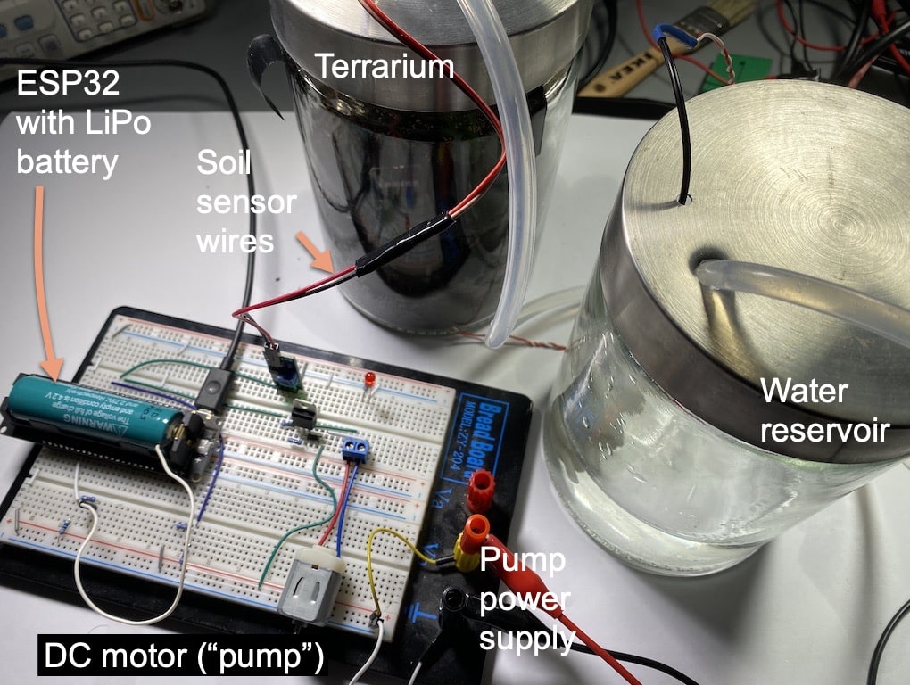
Our current version of the terrarium controller consists of two parts:
Terrarium
At the terrarium side, I use an ESP32 dev kit that reads the sensors and controls the motor. The ESP32 does not make any decisions. All decision making is delegated to Node Red which is running on a Raspberry Pi. More about this in a moment.
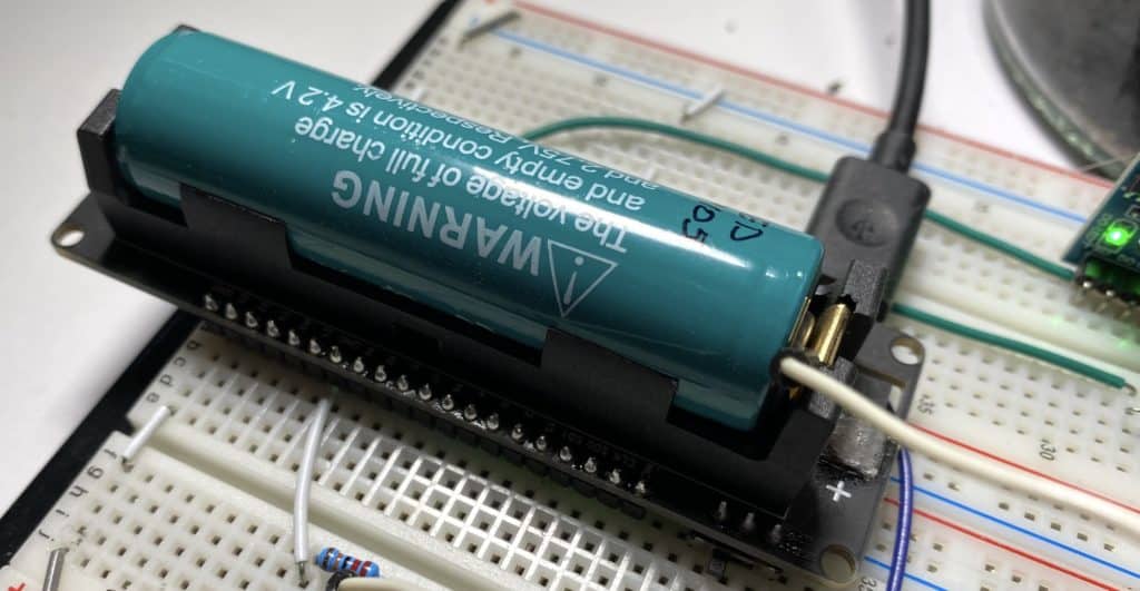
The ESP32 devkit I used contains an integrated LiPo holder and charging circuit, plus a switch. I find this combination very convenient for projects like this. I originally purchased this devkit to make a garage door monitor, but I repurposed it for the terrarium.
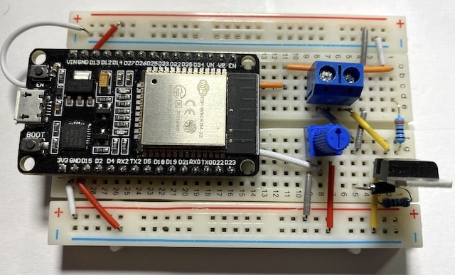
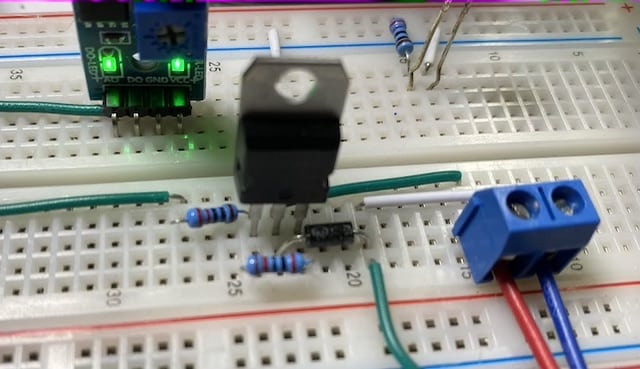
Apart from the TTGO ESP32 devkit picture below, I also tested my circuit and sketch on a “standard” ESP32 devkit V1, which I used in ESP32 For Busy People. As I expected, it worked properly, no worries. You can see that the circuit is small enough to fit in a mini breadboard. I used a potentiometer to simulate the soil sensor. The top power rail is for the motor, and the bottom is for the sensor.
Still at the terrarium side, the circuit includes an analog soil humidity sensor, like this one:
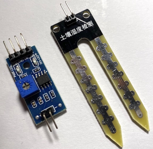
This sensor will give a high analog output when the humidity is low, and low output when the humidity is high. With a bit of trial and error, we can work out the threshold after which the controller must turn on the pump (and below which to turn it off).
The motor is controlled by a simple TIP122 switch. When the signal from the ESP32 goes high, the TIP122 turns on the motor. I decided to keep setup separate power supplies for the motor and for the ESP32 so that if the motor drains its battery, the ESP32 will still be able to notify me via an email, text message etc.
While you can run this controller with a mains power supply, I wanted to go “off-grid” and use batteries. I had recently completed an experiment where I used a Lipo battery-powered ESP32 dev kit. In the experiment, I wanted to find out how long the ESP32 would last simply blinking an LED, of a fully charged battery.
First, I did the experiment without using any sleep modes. Just blink the build-in LED once per second. Total duration: 40 hours.
Second, I repeated the experiment by getting the ESP32 to sleep, then wake up to blink its LED, then go back to sleep. The result was amazing. Total duration: 31.1 days!!!
Curious about my ESP32 battery experiment?
If you are curious, I used this ESP32, here are the individual sketches:
- The non-sleeping sketch.
- The sleeping sketch.
- This sketch is useful for reading the EEPROM.
- And this sketch is for resetting the counter.
I used the EEPROM to record the total number of blinks before battery going kaput.
I did not end up using this discovery in my terrarium controller because the sleep mode does not play well with Wifi functionality. The preservation of the MCU battery power through sleep is an improvement that I will look into later.
The last two component of the circuit on the terrarium side are the voltage divider that I use to measure the two battery voltage levels.
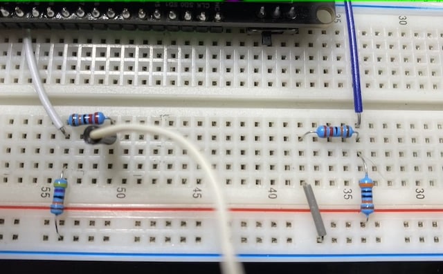
I have connected the signal from the voltage dividers to two analog pins on the ESP32. When the voltage drops below a certain level, I can get the application to send me an email via IFTTT so I can charge the battery.
The sketch that is running on the ESP32 is fairly simple since it’s only tasks are to get readings from the analog sensors, turn the motor on and off, and communicate with Node Red via Wifi. I’ll publish the sketch once I have finished work on it.
Node Red
Node Red is amazing. I had played with it in the past, but I had not build something with it. I was actually in search for a project that I could build on Node Red when Ari gave me the idea of the terrarium controller.
Node Red is a flow-based, graphical programming tool that is amazing at integrating a variety of hardware and software resources. It is open-source, invented in the 1970s by J. Paul Morrison, originally developerd by IBM’s Emerging Technology Services, and is now now a part of the JS Foundation.
It is a powerful tool, with a surprisingly short learning curve. You can have it up and running within minutes, and create your first flow within seconds.
You can install Node Red on any computer, it doesn’t need to be a Raspberry Pi. But since I have a few Pis around, I used them.
With Node Red, you create flows that contain nodes. Nodes can exchange data, can interact with resources such as MQTT brokers and web services. They can contain small code snippets written in (of course) Javascript.
Node Red comes with many common nodes pre-installed, but can also be extended by installing Nodes and even completed flows created by its users. This is the equivalent of third-party libraries in the Arduino world.
This repository contains thousands of shared nodes and flows.
Here’s an example of a flow, which I developed for the terarrium controller.
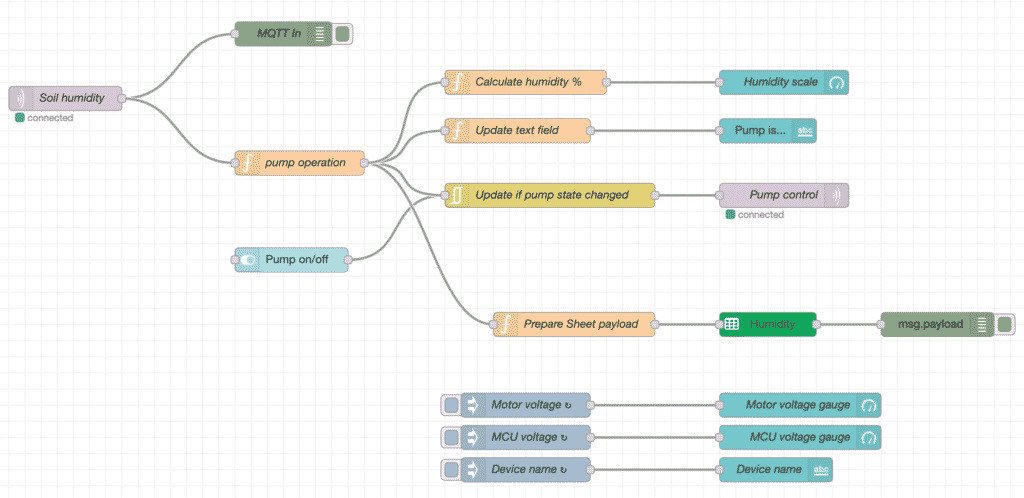
Easy to read, isn’t it? Each node performs a specific action, and you can configure it by double-clicking on it. For example, if you double-click on a function node, you will see something like this:
Simple Javascript operates on input data or variable data and creates an output that the next node can use.
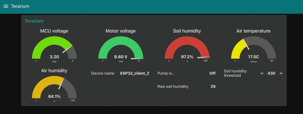
With a contributed set of nodes, you can create a dashboard.
Remember how one of my terrarium requirements was the ability to control it via a web interface? Done!
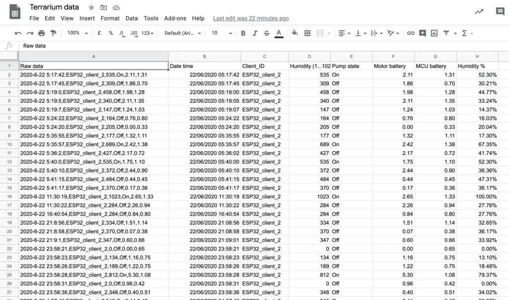
This terrarium flow even takes care of data-logging (via a Google Sheet node) to Google Sheet:
I am very pleased about this this project worked out. There’s still plenty of work to do. For example, I still have to setup IFTTT battery level notifications, and also want to explore other integrations with web services using webhooks and HTTP requests.
I’m very curious to hear some feedback from you, the reader.
How would you approach a project like this?
Do you have any suggestions for experiments I can try, or features I can implement?
Would you like this project to become a course so you can create your own terrarium (or whatever you want to control with Node Red and an ESP32)?
Let me know in the comments below.
Update, July 3, 2020
I just received the terrarium PCB from PCBWay.
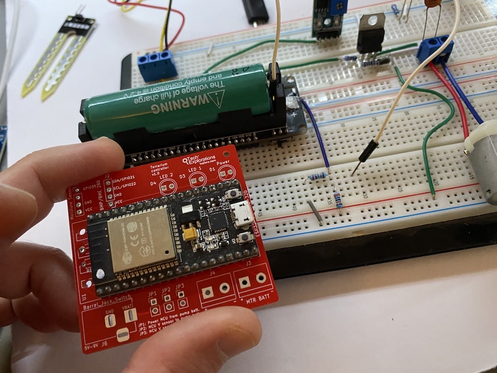
However, even though it is brand new, it is obsolete!
When I designed the PCB, I was thinking of using the regular devkit v1 (that you can see on the PCB in the photo).
But later, I decided to use the a devkit with integrated Li-Po holder and charger. The headers for this devkit is a little wider, so I will have to edit the design.
I also added two new features:
- A DHT22 sensor in a special enclosure so I can get air temperature and humidity (inside the terrarium).
- An automatic water-pump cut-off. I added this because I realised that my small terrarium need only a small amount of water. The pump is controlled by the Node Red flow, so if WiFi communication falls over when the pump is on, it will not turn off and the terrarium will flood. With the new fail-safe, the pump will only operate for 5 seconds, and then the controller will need to restart it if soil humidity is still below the threshold.
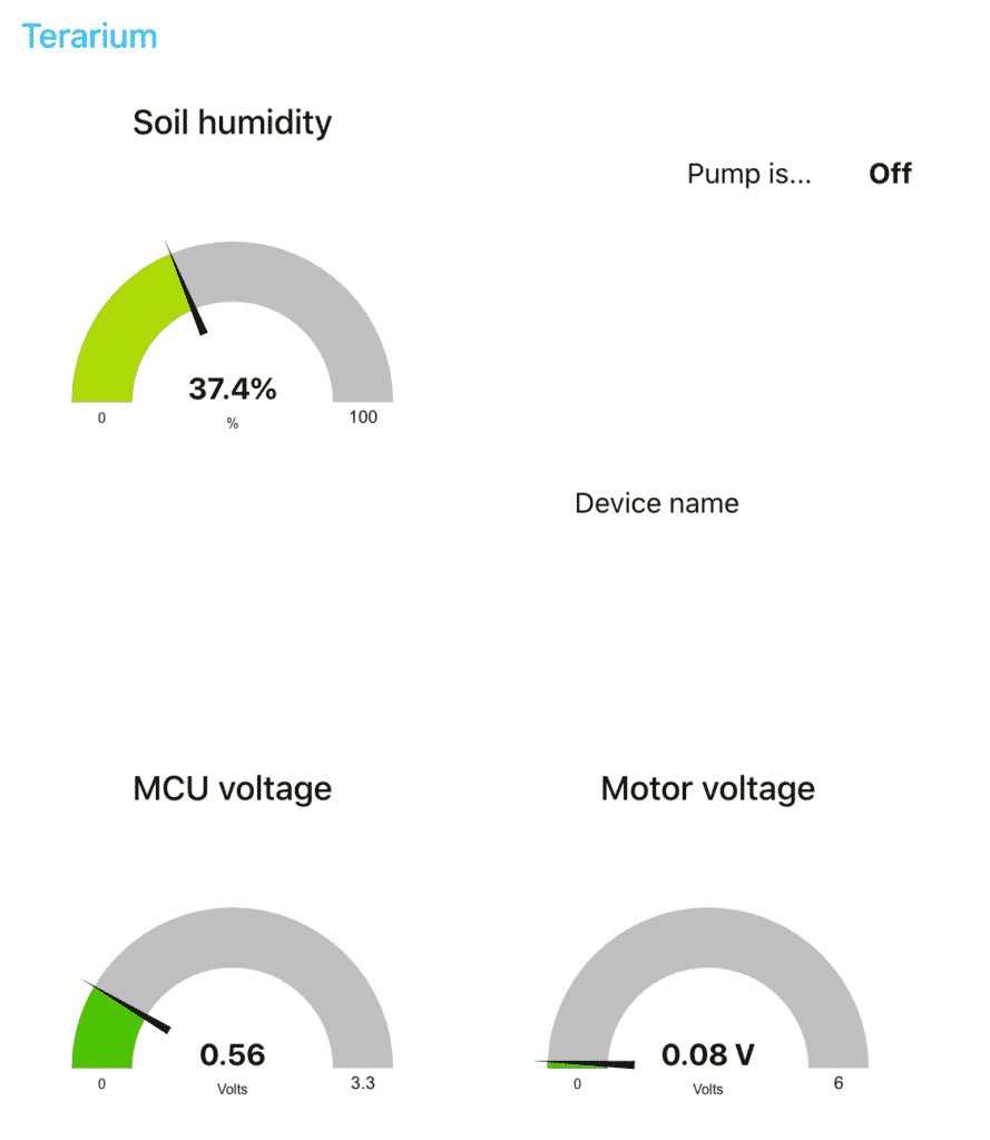
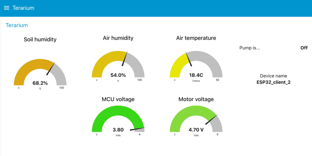
Here’s the current dashboard:
I plan a few additions. Apart from a new PCB, I also want to design a case.
Anything I am missing?
Update: July 8 2020
I have assembled the PCB and did some testing:
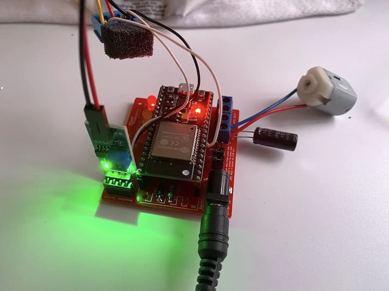
I may actually go ahead with this PCB.
Over the weekend, I tested both the Li-Po version of the ESP32, and the regular ESP32 with the PCB.
I found that the battery-powered version does not provide much of an advantage. The battery doesn’t last more than 2-3 days. Because it is not possible to put the controller to sleep while the WiFi is on, I concluded that this project must be powered externally.
I know that the new ESP32-2S will have the ability to put the MCU to sleep even with the WiFi on automatically. So, I may test that option when I get an actually ESP32-2S (I am waiting for one to arrive from China).
It is possible to power the MCU and the motor via a wall power supply, as long as it can provide 5V to 9V and at least 1A of power. I have added a capacitor on the motor terminals to help with the noise (which can disturb the sensor).
When I designed the current version of the PCB I did not include a connector for the DHT22 sensor, so I just wired it directly on the MCU GPIO 25. I’ll fix that in the next iteration of the PCB.
I also had a mishap that I am investigating. I filled the water container to the rim, thinking that the system is now reliable enough to not have to worry about flooding the terrarium.
Alas… I was distracted with work and next thing you know is the terrarium is flooded. I am not show what caused this. I am researching the root cause, and also looking into the inclusion of a fail-safe to prevent this from happening again.
Also, the dashboard looks much cooler in black: