
Jump to a segment…
- AVR-C for Arduino Makers
- Benefits of using the AVR-GCC compiler
- What is needed for AVR-C / AVR-GCC programming?
- Arduino IDE for AVR-C / AVR-GCC programming
- AVR-C programming the hard way
- AVR-C programming the easy way (using Arduino IDE)
- What is “DDRD”?
- Change the LED to Arduino Pin 13
- What does “1 << LED_PIN” do?
- Why is the value of PB5 “5”?
- What is the meaning of “|=”?
- What is “^=”?
- What is the relation between the DDRB and PORTB registers?
- Conclusion and next steps
If you are familiar with the Arduino Uno (and other classic Arduino boards), you probably know that its brain is the ATMEGA328P microcontroller. If you have done any programming on a classic Arduino, you probably used the “Arduino language” with the Arduino IDE.
This is how most of us learned embedded programming. Embedded programming is a specific type of programming that works with embedded systems. Embedded systems are computer systems with a dedicated function within a larger mechanical or electrical system. They are typically designed to perform a specific task, often with real-time computing constraints. The thing about embedded programming is that it involves writing code that is efficient, reliable, and able to operate under these constraints.
Embedded programmers need to have a strong understanding of both software development and the hardware on which their code will run. They often work in C or C++, although high-level languages like Python and JavaScript are becoming more common in certain applications.
Think of the ATMEGA328P MCU in the Arduino Uno, and compare it to a Raspberry Pi, a tiny computer. The MCU has a fraction of the storage and RAM of even the tiniest computer.
Learning embedded programming with the Arduino language and the Arduino IDE made it much easier for learners to understand the basics. In exchange for the simplicity, we lost visibility of some of the intricacies of embedded programming, such as having full control and access to the hardware of the MCU (such as its registers). We wrote code that was less efficient than it could have been.
AVR-C for Arduino Makers
If you are familiar with the Arduino language and the Arduino IDE, you might wonder what it is like to be programming your Arduino Uno directly in its native C language.
As I’ll show you in this article, this is easier than you might think, as long as you understand the basics.
Firstly, what is AVR-C?
AVR-C isn’t a distinct programming language but uses the C programming language specifically for AVR microcontrollers, such as those produced by Atmel (now owned by Microchip).
AVR microcontrollers can be programmed using the standard C language but with specific libraries and functions that interface with the hardware of these microcontrollers. This includes libraries for handling GPIO (General-Purpose Input/Output), timers, interrupts, and various communication protocols like UART, SPI, and I2C.
When programming in C for AVR microcontrollers, developers often use the AVR-GCC compiler, which is a version of the GNU GCC compiler optimized for AVR. This allows the developer to write efficient code directly controlling the microcontroller’s hardware. This is often done in an integrated development environment (IDE) such as Atmel Studio or the Arduino IDE. However, the Arduino IDE typically abstracts away much of the hardware-specific code for ease of use.
So, “AVR-C” isn’t an official term or language, but it’s occasionally used to refer to the practice of writing C code specifically for AVR microcontrollers.
Benefits of using the AVR-GCC compiler
Learning to use the AVR-GCC compiler for your Arduino UNO or ATMEGA328P (or other AVR MCUs) is not trivial. It requires learning how to use the toolchain and the AVR-C language. It also requires you to learn and understand the hardware architecture of the microcontroller because, with AVR-C, you will need to work directly with the hardware, not with its abstraction.
However, there are a few reasons why one might choose to use AVR-GCC directly and that justify the effort:
- Full Control and Flexibility: Using AVR-GCC and writing code in pure C or C++ gives you full control over the microcontroller and its peripherals. This can be necessary for more advanced projects where fine control over hardware resources is needed.
- Optimization: Arduino’s ease of use comes with some overhead. When you need to optimize your code for speed or size, using AVR-GCC directly can provide more options for optimization.
- Learning: If your goal is to learn more about microcontrollers and embedded systems programming, using AVR-GCC directly can provide a better understanding of how things work under the hood.
- Portability: Code written in pure C or C++ for AVR-GCC can be more portable to other microcontrollers or platforms, whereas Arduino code often relies on Arduino-specific libraries.
- Professional Development: If you’re considering a career in embedded systems, experience with a toolchain like AVR-GCC can be valuable. Professional development often involves more direct control over the hardware than the Arduino environment provides.
Remember that each project is unique, and the best tools depend on the requirements and the person or team working on it. Both Arduino and AVR-GCC are valid choices with their strengths and weaknesses.
What is needed for AVR-C / AVR-GCC programming?
Programming AVR microcontrollers can be done in several ways, including Assembly language or higher-level languages like C or C++. The most common method is to use the C programming language in combination with the AVR-GCC compiler, which is part of the AVR Toolchain. This toolchain provides a complete set of tools for developing, compiling, and debugging AVR applications.
To get started with AVR programming, you’ll typically need the following:
- An AVR microcontroller or development board (e.g., Arduino, which uses the AVR architecture)
- The AVR Toolchain (AVR-GCC, AVRDUDE, and other utilities)
- A programmer or debugger (e.g., USBasp, AVRISP mkII, Atmel-ICE)
- A suitable Integrated Development Environment (IDE) like Atmel Studio or Visual Studio Code with the PlatformIO extension
Once you have the necessary hardware and software, you can start programming your AVR microcontroller by writing code, compiling it using the AVR-GCC compiler, and then uploading the compiled program to the microcontroller using a programmer or debugger.
Arduino IDE for AVR-C / AVR-GCC programming
As an Arduino programmer, talking about the “AVR Toolchain”, the “AVR-GCC compiler”, “programmer/debuggers”, etc., may be confusing and even scary. Most of us are used to starting up the Arduino IDE, writing a sketch, and uploading it to the Arduino Uno with the click of the mouse. Installing complicated command-line software, wiring up the debugger to the MCU, compiling the program, and uploading it may seem like a Herculean task.
Luckily, we already have the Arduino IDE. We can use the Arduino IDE for programming an ATmega328P microcontroller directly in C (AVR-C). The Arduino IDE uses the AVR-GCC compiler under the hood, the same compiler used for AVR-C programming. While the Arduino IDE is typically used with Arduino-specific libraries and the Wiring language (a set of C/C++ functions), you can write direct C/C++ code without using the Arduino-specific functions.
In this article, I will show you how to use the Arduino IDE to write an AVR-C program that blinks the built-in LED.
But first, I will show you how to do the same tasks the hard way.
AVR-C programming the hard way
For this example, I will use the AVR toolchain to write, compile and upload a program that makes the LED on an Arduino UNO board blink. In this example, let’s assume that the toolchain is already installed.
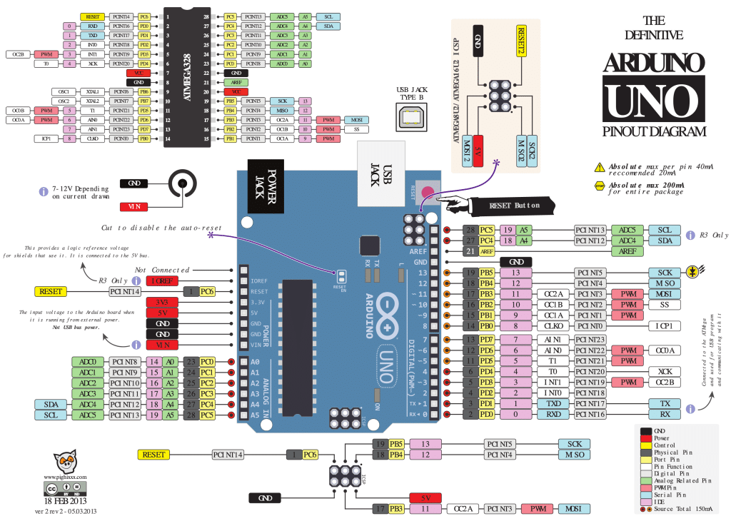
You will also need a pinout diagram that shows the native pin definitions for the ATMEGA328P alongside the familiar Arduino pin definitions. The best such diagram I have found is this one, from Pighixxx, now available only in the Wayback Machine and Wikimedia.
The program
Here’s a simple example of a program that will make an LED connected to the ATmega328P’s PD2 pin (digital pin 2) blink on and off every 1 second. You can refer to the pinout diagram to see how the native pin PD2 is our familiar Arduino pin 2.
This example uses the C programming language and assumes you use the AVR-GCC compiler.
#include <avr/io.h>
#include <util/delay.h>

#define LED_PIN PD2
#define LED_DDR DDRD
#define LED_PORT PORTD

int main(void) {
    // Set the LED_PIN as output
    LED_DDR |= (1 << LED_PIN);

    while (1) {
        // Toggle the LED state
        LED_PORT ^= (1 << LED_PIN);

        // Wait for 1 second (1000 milliseconds)
        _delay_ms(1000);
    }

    return 0;
}
Don’t worry about the specifics of this program. I will explain everything later.
To compile and upload this program to your ATmega328P, you can create a Makefile with the following content (assuming the source code is in a file named “main.c”):
MCU = atmega328p
F_CPU = 16000000UL
CC = avr-gcc
CFLAGS = -Os -mmcu=$(MCU) -DF_CPU=$(F_CPU)
OBJCOPY = avr-objcopy
AVRDUDE = avrdude
PROGRAMMER = -c usbasp -p $(MCU)

all: main.hex

main.hex: main.elf
    $(OBJCOPY) -O ihex -R .eeprom $< $@

main.elf: main.o
    $(CC) $(CFLAGS) -o $@ $<

main.o: main.c
    $(CC) $(CFLAGS) -c -o $@ $<

upload: main.hex
    $(AVRDUDE) $(PROGRAMMER) -U flash:w:$<:i

clean:
    rm -f main.o main.elf main.hex
You must change the PROGRAMMER variable in the Makefile according to the programmer you’re using. This example assumes a USBasp programmer.
To compile the code, “run make” in the terminal, and to upload the compiled program to the microcontroller, “run make upload“.
The LED connected to the PD2 pin should start blinking on and off every 1 second.
AVR-C programming the easy way (using Arduino IDE)
Let’s repeat this experiment using the Arduino IDE. Here are the steps involved:
- If (for some reason) you don’t already have the Arduino IDE on your computer, get it from the official website: Arduino IDE Download.
- Open the Arduino IDE and create a new sketch by clicking on
File>New. - Replace the default code in the new sketch with the example code provided:
#include <avr/io.h>
#include <util/delay.h>

#define LED_PIN PD2
#define LED_DDR DDRD
#define LED_PORT PORTD

int main(void) {
    // Set the LED_PIN as output
    LED_DDR |= (1 << LED_PIN);

    while (1) {
        // Toggle the LED state
        LED_PORT ^= (1 << LED_PIN);

        // Wait for 1 second (1000 milliseconds)
        _delay_ms(1000);
    }

    return 0;
}- Save the sketch with a suitable name, such as “Blinking_LED”.
- Before compiling the sketch, select the appropriate board and processor. For the ATmega328P, you can select the “Arduino Uno” board for the ATmega328P microcontroller. Go to
Tools>Board>Arduino AVR Boards>Arduino Uno. - Also, ensure that the correct serial port is selected. Go to
Tools>Portand choose the appropriate serial port corresponding to your Arduino Uno or other ATmega328P-based board. - Now, you can compile the sketch by clicking on the checkmark icon in the upper left corner of the IDE or by selecting
Sketch>Verify/Compile. - After the sketch has been successfully compiled, you can upload it to your board by clicking on the right arrow icon in the upper left corner of the IDE or by selecting
Sketch>Upload.
Once the sketch has been uploaded to your ATmega328P-based board, the LED connected to the PD2 pin should start blinking on and off every 1 second.
Here’s my Arduino IDE with the program:
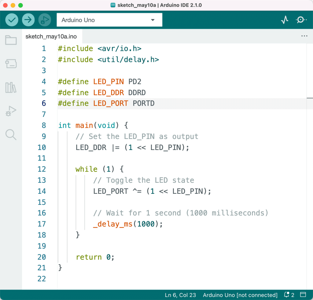
If you have connected an LED to Arduino pin 2 (the native or hardware pin PD2), it will be blinking at a rate of 1 Hz.
At this point, simply looking at this program would raise several questions. I’ll try to answer them next.
To get to the source of these answers, you must look at the datasheet for the ATMEGA328P. This is the best reference document for the ATmega328 microcontroller’s register architecture, and other detailed information about its features and functionalities is the ATmega328P datasheet. The datasheet is provided by Microchip Technology (which acquired Atmel).
The datasheet contains comprehensive information about the microcontroller, including its memory organization, I/O ports, registers, timers, interrupts, and peripherals. It also provides electrical characteristics, pin configurations, and programming information. By referring to the datasheet, you can gain a deep understanding of the ATmega328P and how to work with it effectively.
What is “DDRD”?
DDRD is an I/O register in the ATmega328P microcontroller that stands for “Data Direction Register D”. The ATmega328P has several 8-bit I/O ports (Port B, Port C, and Port D), each with its corresponding Data Direction Register (DDRB, DDRC, and DDRD, respectively).
The Data Direction Registers are used to configure the individual pins of the I/O ports as input or output. Each bit in the register corresponds to a specific pin in the port. If a bit is set to 1, the corresponding pin is configured as an output. If a bit is set to 0, the corresponding pin is configured as an input.
In the previous example, #define LED_DDR DDRD defines a macro named LED_DDR that represents the Data Direction Register D. The line LED_DDR |= (1 << LED_PIN); sets the specified bit in the DDRD register to configure the corresponding pin (PD2) as an output.
To summarize, DDRD is a register that controls the data direction (input or output) of the pins in Port D of the ATmega328P microcontroller.
Change the LED to Arduino Pin 13
As I am too lazy to connect an LED to PD2, I prefer to use the LED that is already available on the Arduino Uno board. This pin is connected to Arduino pin 13. As per the diagram, Arduino Pin 13 = native pin PB5.
Pin PB5 belongs to Port B of the ATmega328P microcontroller. The registers associated with Port B are:
- PORTB (Port B Data Register): This register controls the output state (high or low) of the pins configured as outputs in Port B.
- PINB (Port B Input Pins Address): This register reads the input state (high or low) of the pins configured as inputs in Port B.
- DDRB (Data Direction Register B): This register configures the pins in Port B as either inputs or outputs.
In summary, pin PB5 is associated with the PORTB, PINB, and DDRB registers for output state control, input state reading, and data direction configuration.
With this information, I can re-write the example program like this:
#include <avr/io.h>
#include <util/delay.h>

#define LED_PIN PB5
#define LED_DDR DDRB
#define LED_PORT PORTB

int main(void) {
    // Set the LED_PIN as output
    LED_DDR |= (1 << LED_PIN);

    while (1) {
        // Toggle the LED state
        LED_PORT ^= (1 << LED_PIN);

        // Wait for 1 second (1000 milliseconds)
        _delay_ms(1000);
    }

    return 0;
}
Upload it to the Arduino, and you will see the built-in LED blink.
What does “1 << LED_PIN” do?
In the code “1 << LED_PIN“, the “<<” operator is called “bitwise left shift” (see bitwise shift operators on Wikipedia). It shifts the bits of the number on its left (in this case, 1) to the left by the number of positions specified on its right (in this case, LED_PIN).
Let’s break it down using the updated example code where LED_PIN is defined as PB5. In this case, the value of LED_PIN is 5. The binary representation of the number 1 is:
0000 0001When we shift the bits of 1 to the left by 5 positions, we get:
0010 0000This operation is useful for microcontroller registers because it allows you to target a specific bit in the register. In the example code, the left shift sets, clears, or toggles the bit corresponding to the LED pin in the Data Direction Register (DDR) and the PORT register.
For example, when configuring the LED pin as an output, the code “LED_DDR |= (1 << LED_PIN);” sets the corresponding bit in the DDR register without affecting the other bits. Similarly, when toggling the LED state, the code “LED_PORT ^= (1 << LED_PIN);” flips the bit corresponding to the LED pin in the PORT register without affecting the other bits.
Why is the value of PB5 “5”?
The value of PB5 is “5” because it represents the fifth bit in the Port B registers (PORTB, PINB, and DDRB) of the ATmega328P microcontroller. In the context of the port registers, each pin is represented by its position within the 8-bit register. The naming convention PxY, where x refers to the port letter (A, B, C, or D) and Y is the pin number (0-7), helps to identify the specific bit in the register associated with that pin.
Here’s a breakdown of the Port B pins and their corresponding bit positions:
- PB0: Bit 0
- PB1: Bit 1
- PB2: Bit 2
- PB3: Bit 3
- PB4: Bit 4
- PB5: Bit 5
- PB6: Bit 6
- PB7: Bit 7
Thus, when referring to PB5, its value as an index in the port registers is 5. This value is used in bitwise operations, such as shifting or masking, to target the specific bit related to the PB5 pin.
What is the meaning of “|=”?
The “|=” operator is a compound assignment operator in the C programming language, which combines the bitwise OR operator (|) with the assignment operator (=). It performs a bitwise OR operation between two operands and then assigns the result back to the left operand.
Here’s a breakdown of how the “|=” operator works:
- Perform a bitwise OR operation between the left and right operands.
- Assign the result of the bitwise OR operation to the left operand.
For example, consider the following code:
LED_DDR |= (1 << LED_PIN);In this code, LED_DDR represents the Data Direction Register for a specific port (e.g., DDRB for Port B) and LED_PIN the pin number (e.g., 5 for PB5). The expression “(1 << LED_PIN)” creates a bitmask with a single bit set at the position corresponding to the LED pin. The “|=” operator then performs a bitwise OR operation between the current value of the LED_DDR register and the bitmask, and assigns the result back to LED_DDR.
This operation aims to set the bit corresponding to the LED pin in the Data Direction Register as output without affecting the other bits in the register. This common technique is used in microcontroller programming for manipulating specific bits in registers while leaving the other bits unchanged.
What is “^=”?
The “^=” operator is another compound assignment operator in the C programming language, which combines the bitwise XOR (exclusive OR) operator (^) with the assignment operator (=). It performs a bitwise XOR operation between two operands and then assigns the result back to the left operand.
Here’s a breakdown of how the “^=” operator works:
- Perform a bitwise XOR operation between the left and right operands.
- Assign the result of the bitwise XOR operation to the left operand.
For example, consider the following code:
LED_PORT ^= (1 << LED_PIN);In this code, LED_PORT represents the PORT register for a specific port (e.g., PORTB for Port B), and LED_PIN represents the pin number (e.g., 5 for PB5). The expression “(1 << LED_PIN)” creates a bitmask with a single bit set at the position corresponding to the LED pin. The “^=” operator then performs a bitwise XOR operation between the current value of the LED_PORT register and the bitmask, and assigns the result back to LED_PORT.
This operation aims to toggle (flip) the bit corresponding to the LED pin in the PORT register. The XOR operation has the property that when one operand is 1, and the other is 0, the result is 1, and when both operands are the same, the result is 0. Therefore, when XOR is applied with a bitmask containing only one bit set, it flips the corresponding bit in the register, changing its state from 0 to 1 or vice versa while leaving the other bits unchanged.
This technique is commonly used in microcontroller programming to toggle the state of specific pins (e.g., turning an LED on and off) without affecting the other pins in the port.
What is the relation between the DDRB and PORTB registers?
The DDRB (Data Direction Register B) and PORTB (Port B Data Register) are two registers associated with Port B of the ATmega328P microcontroller. They work together to control the I/O functionality of the pins in Port B. The relationship between these registers can be explained as follows:
- DDRB (Data Direction Register B): This 8-bit register configures the individual pins in Port B as either inputs or outputs. If a bit in DDRB is set to 1, the corresponding pin in Port B is configured as an output. If a bit in DDRB is set to 0, the corresponding pin in Port B is configured as an input.
- PORTB (Port B Data Register): This 8-bit register serves a dual purpose:
- For pins configured as outputs (DDRB bit is 1): Writing a 1 to a bit in the PORTB register sets the corresponding pin in Port B to a HIGH state (usually +5V or +3.3V, depending on the microcontroller’s operating voltage). Writing a 0 to a bit in the PORTB register sets the corresponding pin in Port B to a LOW state (0V or GND).
- For pins configured as inputs (DDRB bit is 0): Writing a 1 to a bit in the PORTB register enables the internal pull-up resistor for the corresponding pin in Port B. Writing a 0 to a bit in the PORTB register disables the internal pull-up resistor.
The DDRB and PORTB registers are used together to control the behaviour of the pins in Port B. By setting the appropriate bits in the DDRB register, you can configure the pins as either inputs or outputs. Then, by writing to the corresponding bits in the PORTB register, you can control the output state of the pins (for output pins) or enable/disable the internal pull-up resistors (for input pins).
For example, to set pin PB5 as output and turn it HIGH, you would set bit 5 in the DDRB register and set bit 5 in the PORTB register:
DDRB |= (1 << PB5); // Set PB5 as an output
PORTB |= (1 << PB5); // Set PB5 HIGH
Conclusion and next steps
I hope this article has sparked your interest in diving deeper into embedded programming. Remember, the fascinating world of AVR microcontrollers is just the beginning! The skills you acquire from working with MCUs like the ATMEGA328 are versatile and easily applicable to many other architectures. If you’re already familiar with Arduino programming, that’s a great starting point. It lays a solid foundation for further delving into the engaging realm of embedded programming. In other words, you can use your knowledge of AVR programming and architecture to continue you learning in other MCU architectures, such as:
- ARM Cortex-M: The ARM Cortex-M series is a range of 32-bit RISC (Reduced Instruction Set Computing) cores for microcontrollers. They are designed for real-time operating systems and are used in various applications. Popular Cortex-M microcontrollers include the STM32 series from STMicroelectronics and the LPC series from NXP.
- PIC: PIC microcontrollers are a family of microcontrollers made by Microchip Technology, which now owns Atmel and the AVR architecture. PIC microcontrollers come in 8-bit, 16-bit, and 32-bit varieties.
- MSP430: The MSP430 is a mixed-signal microcontroller family from Texas Instruments. They are designed for low power consumption and are often used in battery-powered devices.
- 8051: The 8051 is an older microcontroller architecture originally developed by Intel in the 1980s. It’s still used today in some applications and has been developed further by several other manufacturers.
- ESP8266 / ESP32: The ESP8266 and ESP32 are microcontrollers developed by Espressif Systems. They have built-in Wi-Fi capabilities and are popular in Internet of Things (IoT) applications.
- RISC-V: RISC-V is an open-source instruction set architecture (ISA) based on established RISC principles. While still relatively new, it has seen increased adoption in recent years, including microcontroller designs.
Virtually all of the microcontrollers that you have used or heard about belong to one of the aforementioned architectures, including these:
- ATmega328P is the microcontroller used in the Arduino Uno and many other Arduino boards. It’s an 8-bit AVR microcontroller with 32KB of flash memory and 2KB of SRAM.
- ESP8266 and ESP32: These microcontrollers from Espressif are popular for their built-in Wi-Fi capabilities, making them ideal for IoT applications.
- STM32 Series: These are a family of 32-bit microcontrollers based on the ARM Cortex-M cores made by STMicroelectronics. They come in various configurations with different core types, memory sizes, and peripheral features.
- PIC Microcontrollers: Microchip’s PIC microcontrollers are popular for various applications. They come in 8-bit, 16-bit, and 32-bit varieties.
- Teensy 3.x/4.x: The Teensy boards are a series of microcontroller boards that pack a lot of power in a small form factor. They use various ARM Cortex-M microcontrollers.
- ATmega2560: This is the microcontroller used in the Arduino Mega. It’s an 8-bit AVR microcontroller with 256KB of flash memory and 8KB of SRAM.
- MSP430: These microcontrollers from Texas Instruments are known for their low power consumption and are often used in battery-powered devices.
- nRF52 Series: Nordic Semiconductor’s nRF52 series microcontrollers are popular for their built-in Bluetooth Low Energy (BLE) capabilities.
- SAM D21: This is the microcontroller used in the Arduino Zero and MKR boards. It’s a 32-bit ARM Cortex-M0+ microcontroller.
- Raspberry Pi Pico’s RP2040 is a microcontroller developed by the Raspberry Pi Foundation. It’s a dual-core ARM Cortex-M0+ microcontroller with 264KB of on-chip SRAM.
If you are curious, I can suggest a path forward, keeping my focus on the AVR-C and AVR-GCC universe.
Here’s my suggested learning path for programming in AVR-C:
- Fundamentals of C programming: Before diving into AVR-C, it’s important to understand the fundamentals of C programming. This includes data types, operators, control structures, arrays, pointers, functions, and more. There are many online resources and books for learning C, such as “C Programming Absolute Beginner’s Guide (3rd Edition)” by Greg Perry and Dean Miller.
- Microcontroller Basics: Learn about microcontroller basics such as what a microcontroller is, the difference between a microcontroller and a microprocessor, and understanding the basic components of a microcontroller like CPU, memory, I/O ports, and timers.
- Introduction to AVR Microcontrollers: Familiarize yourself with AVR microcontrollers, their architecture, and their features. The ATmega328P, used in many Arduino boards, is a good starting point.
- AVR-GCC and AVR Libc: Learn about the AVR-GCC compiler and AVR Libc, a library of utility functions for AVR microcontrollers. Understand how to install and set up the AVR-GCC toolchain on your system.
- AVR Input/Output Programming: Start with basic programs to blink an LED, then move on to reading button inputs. Understand how to use the DDRx, PINx, and PORTx registers for controlling GPIO.
- Interrupts and Timers: Learn about using interrupts and timers in AVR microcontrollers, their registers, and how to program them.
- Communication Protocols: Understand various communication protocols like UART, SPI, and I2C and how to use them with AVR microcontrollers.
- Working with Sensors and Peripherals: Learn how to interface with different types of sensors and peripheral devices, such as temperature sensors, accelerometers, LCDs, etc.
- Power Management and Optimization: Learn about different power modes in AVR microcontrollers and how to write power-efficient code. Also, understand how to optimize your code for performance.
- Advanced Topics: Once you’re comfortable with the basics, you can delve into more advanced topics like direct memory access (DMA), analog-to-digital converters (ADC), digital-to-analog converters (DAC), and more.
Remember, practical hands-on experience is key when learning about microcontrollers. Try to work on simple projects first, then gradually increase the complexity as you learn more. Books like “AVR Programming: Learning to Write Software for Hardware” by Elliot Williams could also be useful.
Also, take advantage of online communities, tutorials, and documentation. Websites like AVR Freaks, Arduino Stack Exchange, and the official Atmel (Microchip) website have a wealth of information and helpful communities.
Remember, learning to program microcontrollers is a journey. Take your time, enjoy each step, and don’t be afraid to experiment and make mistakes. That’s often when the best learning happens.
Enjoy!