
I am working on a new course on the Arduino IoT Cloud platform. With Arduino IoT Cloud, you can create Internet of Things applications based on compatible Arduino boards and a few selected non-Arduino microcontrollers, such as the ESP32 and the ESP8266. In this context, I tested the DR Robot Firebeetle 2 ESP32-E board, along with several peripherals, with the Arduino IDE (desktop) and the Arduino IoT Cloud platform. In this article, I present the results of these tests.
If you are in a hurry, you can watch the video.
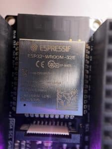
I recently came across the Firebeetle ESP32-E board from DF Robot. It drew my attention because of two reasons:
- It contains the ESP32-E module with the newer ESP32-D0WD-V3 chip.
- DF Robot makes a very clever shield board, which snaps on the Firebeetle and makes it easy to connect peripherals. No breadboards or soldering needed.
I decided to try the Firebeetle ESP32-E with the Firebeetle Expansion Shield and a couple of peripherals. Here’s my setup:
- FireBeetle 2 ESP32-E IoT Microcontroller.
- IO Shield for FireBeetle M0 and ESP32-E.
- Gravity: Terminal Sensor Adapter V2.0.
- Waterproof DS18B20 Digital Temperature Sensor with the Terminal Sensor Adapter V2.0.
- I2C BMI160 6-Axis Inertial Motion Sensor.
Since I was deep into the Arduino IoT Cloud when I got my hands on the Firebeetle, I decided to play with Firebeetle + Arduino IoT Cloud. Does the ESP32E work with Arduino IoT Cloud? How well? Any hiccups?
Here’s what I found.
Testing in the Arduino IDE
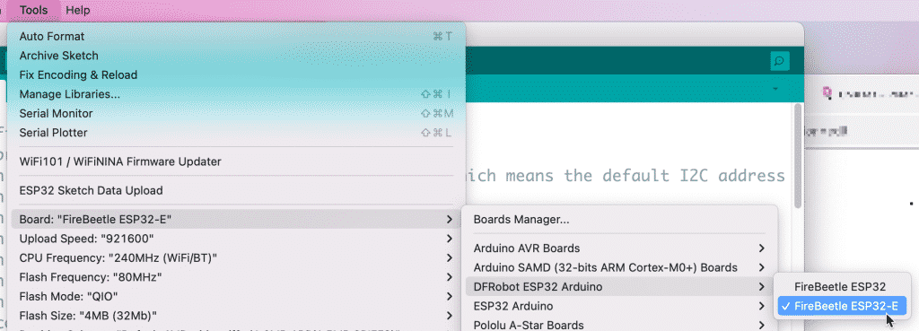
To keep things simple, I followed the instructions from DF Robot and setup the Firebeetle to work with the desktop Arduino IDE. Although you can set up the Arduino IDE to use the generic ESP32 Dev Module board, you will be able to use the specific Fireboard 2 ESP32-E feature by installing the board’s definitions and selecting the “Fireboard ESP32-E” board from the Tools –> Board menu.
In case you are curious, here’s my Arduino IDE’s board manager URLs:
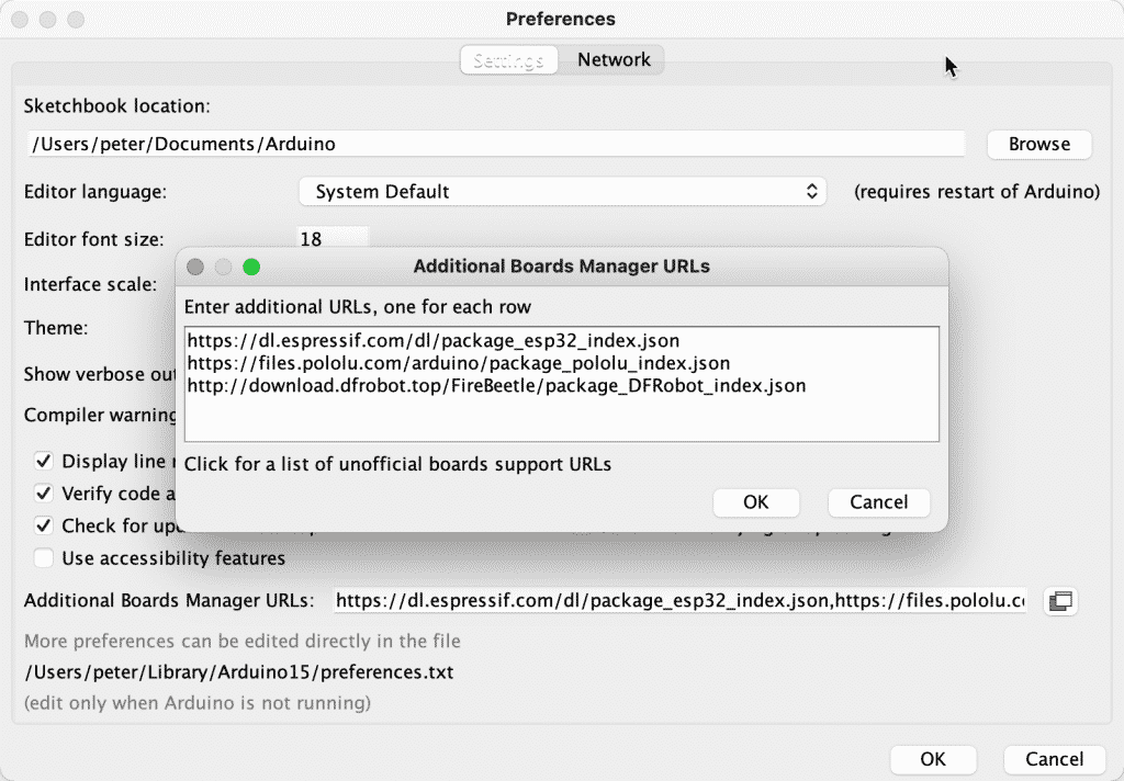
The URL that contain the definitions for the DF Robot boards is:
http://download.dfrobot.top/FireBeetle/package_DFRobot_index.jsonBlink and pin numbers
One “gotcha” moment was when I realised that the Firebeetle has a peculiar way of numbering pins. As an example, let’s take the built-in LED, seen in the board overview below (I have copied this graphic from the DF Robot wiki, I hope it’s ok):
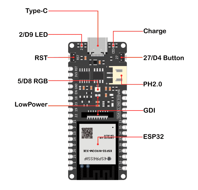
You will find the built-in LED in the top left corner of the board, next to the USB-C connector. Notice that the pin numbering is “2/D9”. You can access this LED by writing to pin “2” or pin “D9”.
To blink the LED, you can use either of these sketches:
- Using “D9”:
void setup() {
  pinMode(D9, OUTPUT);
}
void loop() {
  digitalWrite(D9, HIGH);
  delay(1000);
  digitalWrite(D9, LOW);
  delay(1000);
}
2. Using “2”:
void setup() {
  pinMode(2, OUTPUT);
}

void loop() {
  digitalWrite(2, HIGH);
  delay(1000);
  digitalWrite(2, LOW);
  delay(1000);
}
In the properly configured Arduino IDE, either one works fine.
The FireBeetle also has a built-in button in the top-right corner of the board. You can access it as pin “27” or “D4”. Here’s an example that uses the former option, where pressing the build-in button turns on the build LED:
void setup() {
  pinMode(27, INPUT_PULLUP);
  pinMode(2, OUTPUT);
}

void loop() {
  int sensorVal = digitalRead(27);
  if (sensorVal == HIGH) {
    digitalWrite(2, LOW);
  } else {
    digitalWrite(2, HIGH);
  }
}
It was also easy to get the build-in RGB LED to work, with help from the FastLED library. The RGB LED uses the WS2812 controller and is connected to pin “5/D8”.
Here is an example from the library (“ColorPalette“, I have removed the comments to reduce the size of the code):
#include <FastLED.h>

#define LED_PIN     5
#define NUM_LEDS    1
#define BRIGHTNESS  64
#define LED_TYPE    WS2811
#define COLOR_ORDER GRB
CRGB leds[NUM_LEDS];

#define UPDATES_PER_SECOND 100

CRGBPalette16 currentPalette;
TBlendType    currentBlending;

extern CRGBPalette16 myRedWhiteBluePalette;
extern const TProgmemPalette16 myRedWhiteBluePalette_p PROGMEM;


void setup() {
    delay( 3000 ); // power-up safety delay
    FastLED.addLeds<LED_TYPE, LED_PIN, COLOR_ORDER>(leds, NUM_LEDS).setCorrection( TypicalLEDStrip );
    FastLED.setBrightness(  BRIGHTNESS );

    currentPalette = RainbowColors_p;
    currentBlending = LINEARBLEND;
}


void loop()
{
    ChangePalettePeriodically();

    static uint8_t startIndex = 0;
    startIndex = startIndex + 1; /* motion speed */

    FillLEDsFromPaletteColors( startIndex);

    FastLED.show();
    FastLED.delay(1000 / UPDATES_PER_SECOND);
}

void FillLEDsFromPaletteColors( uint8_t colorIndex)
{
    uint8_t brightness = 255;

    for( int i = 0; i < NUM_LEDS; ++i) {
        leds[i] = ColorFromPalette( currentPalette, colorIndex, brightness, currentBlending);
        colorIndex += 3;
    }
}

void ChangePalettePeriodically()
{
    uint8_t secondHand = (millis() / 1000) % 60;
    static uint8_t lastSecond = 99;

    if( lastSecond != secondHand) {
        lastSecond = secondHand;
        if( secondHand ==  0)  { currentPalette = RainbowColors_p;         currentBlending = LINEARBLEND; }
        if( secondHand == 10)  { currentPalette = RainbowStripeColors_p;   currentBlending = NOBLEND;  }
        if( secondHand == 15)  { currentPalette = RainbowStripeColors_p;   currentBlending = LINEARBLEND; }
        if( secondHand == 20)  { SetupPurpleAndGreenPalette();             currentBlending = LINEARBLEND; }
        if( secondHand == 25)  { SetupTotallyRandomPalette();              currentBlending = LINEARBLEND; }
        if( secondHand == 30)  { SetupBlackAndWhiteStripedPalette();       currentBlending = NOBLEND; }
        if( secondHand == 35)  { SetupBlackAndWhiteStripedPalette();       currentBlending = LINEARBLEND; }
        if( secondHand == 40)  { currentPalette = CloudColors_p;           currentBlending = LINEARBLEND; }
        if( secondHand == 45)  { currentPalette = PartyColors_p;           currentBlending = LINEARBLEND; }
        if( secondHand == 50)  { currentPalette = myRedWhiteBluePalette_p; currentBlending = NOBLEND;  }
        if( secondHand == 55)  { currentPalette = myRedWhiteBluePalette_p; currentBlending = LINEARBLEND; }
    }
}

void SetupTotallyRandomPalette()
{
    for( int i = 0; i < 16; ++i) {
        currentPalette[i] = CHSV( random8(), 255, random8());
    }
}

void SetupBlackAndWhiteStripedPalette()
{
    // 'black out' all 16 palette entries...
    fill_solid( currentPalette, 16, CRGB::Black);
    // and set every fourth one to white.
    currentPalette[0] = CRGB::White;
    currentPalette[4] = CRGB::White;
    currentPalette[8] = CRGB::White;
    currentPalette[12] = CRGB::White;

}

void SetupPurpleAndGreenPalette()
{
    CRGB purple = CHSV( HUE_PURPLE, 255, 255);
    CRGB green  = CHSV( HUE_GREEN, 255, 255);
    CRGB black  = CRGB::Black;

    currentPalette = CRGBPalette16(
                                   green,  green,  black,  black,
                                   purple, purple, black,  black,
                                   green,  green,  black,  black,
                                   purple, purple, black,  black );
}

const TProgmemPalette16 myRedWhiteBluePalette_p PROGMEM =
{
    CRGB::Red,
    CRGB::Gray, // 'white' is too bright compared to red and blue
    CRGB::Blue,
    CRGB::Black,

    CRGB::Red,
    CRGB::Gray,
    CRGB::Blue,
    CRGB::Black,

    CRGB::Red,
    CRGB::Red,
    CRGB::Gray,
    CRGB::Gray,
    CRGB::Blue,
    CRGB::Blue,
    CRGB::Black,
    CRGB::Black
};
Glad to see that all build-in hardware works!
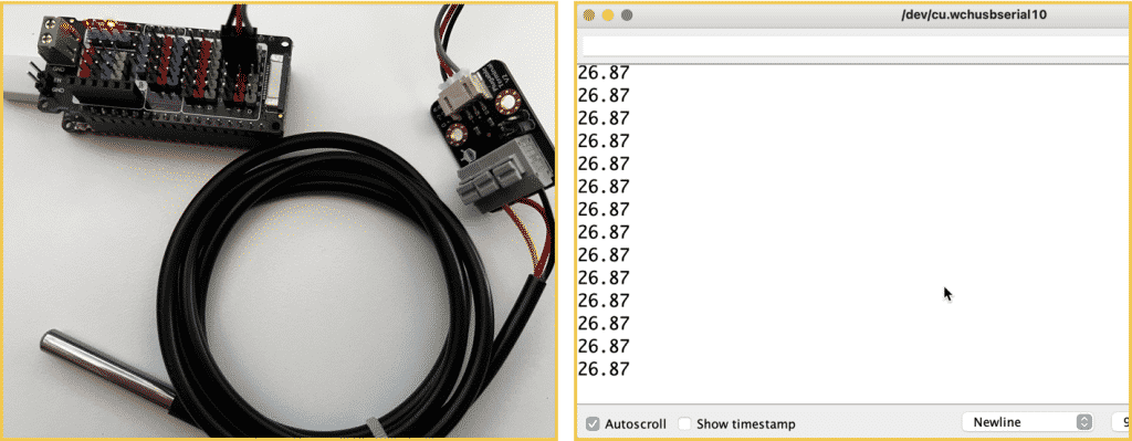
DS18B20 Digital Temperature Sensor + Terminal Sensor Adapter V2.0
I was able to get the DS18B20 to work without any problems. The adapter plug allows me to insert the two wires from the sensor without a screwdriver. Then, I can insert the wires from the adapter into the shield.
I tried out the sample code from the DF Robot wiki, but it didn’t work first try.
The problem?
The sample code regular pin numbers, such as “2” for the digital pins.
Because I’m using the Firebeetle 2, I have to remember to use “D2” in code written for other boards.
Here’s the working version of the sample code for the DS18B20 sensor:
#include <OneWire.h>

int DS18S20_Pin = D2; //DS18S20 Signal pin on digital D2 on the FireBeetle 2

//Temperature chip i/o
OneWire ds(DS18S20_Pin);  // on digital pin 2

void setup(void) {
  Serial.begin(9600);
}

void loop(void) {
  float temperature = getTemp();
  Serial.println(temperature);
  delay(100); //just here to slow down the output so it is easier to read
}


float getTemp(){
  //returns the temperature from one DS18S20 in DEG Celsius
  byte data[12];
  byte addr[8];

  if ( !ds.search(addr)) {
      //no more sensors on chain, reset search
      ds.reset_search();
      return -1000;
  }

  if ( OneWire::crc8( addr, 7) != addr[7]) {
      Serial.println("CRC is not valid!");
      return -1000;
  }

  if ( addr[0] != 0x10 && addr[0] != 0x28) {
      Serial.print("Device is not recognized");
      return -1000;
  }

  ds.reset();
  ds.select(addr);
  ds.write(0x44,1); // start conversion, with parasite power on at the end

  byte present = ds.reset();
  ds.select(addr);
  ds.write(0xBE); // Read Scratchpad


  for (int i = 0; i < 9; i++) { // we need 9 bytes
    data[i] = ds.read();
  }

  ds.reset_search();

  byte MSB = data[1];
  byte LSB = data[0];

  float tempRead = ((MSB << 8) | LSB); //using two's compliment
  float TemperatureSum = tempRead / 16;

  return TemperatureSum;
}
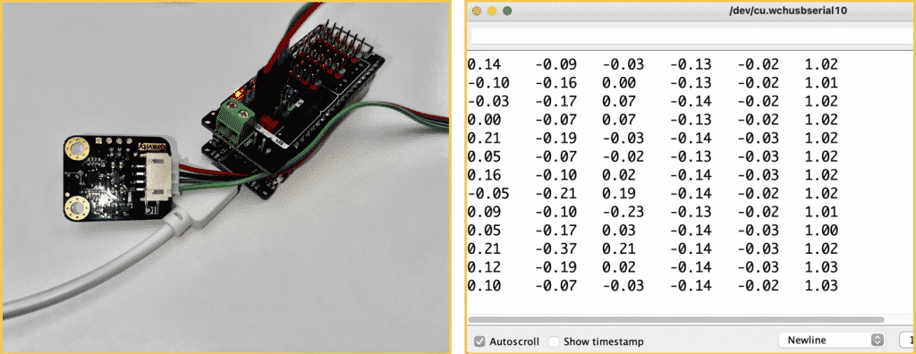
Testing the I2C BMI160 module
Next, I tested the BMI160 breakout. The BMI160 module itself can communicate via I2C or SPI interfaces. However, the DF Robot breakout exposes only the I2C interface. The lack of the SPI option on the BMI160 breakout means that I had no way of testing it with the Arduino IoT Cloud platform, where I had difficulties getting the sensor to work with I2C.
However, in the Arduino IDE, I got the sensor to work quickly. I tried two different libraries, which are forks of each other:
- The DFRobot BMI160 library.
- The BMI160-Arduino library.
Below I copy the DF Robot library because I find it a bit simpler to use:
#include <DFRobot_BMI160.h>

DFRobot_BMI160 bmi160;
const int8_t i2c_addr = 0x69;
void setup(){
  Serial.begin(115200);
  delay(100);

  //init the hardware bmin160
  if (bmi160.softReset() != BMI160_OK){
    Serial.println("reset false");
    while(1);
  }

  //set and init the bmi160 i2c address
  if (bmi160.I2cInit(i2c_addr) != BMI160_OK){
    Serial.println("init false");
    while(1);
  }
}

void loop(){
  int i = 0;
  int rslt;
  int16_t accelGyro[6]={0};

  //get both accel and gyro data from bmi160
  //parameter accelGyro is the pointer to store the data
  rslt = bmi160.getAccelGyroData(accelGyro);
  if(rslt == 0){
    for(i=0;i<6;i++){
      if (i<3){
        //the first three are gyro datas
        Serial.print(accelGyro[i]*3.14/180.0);Serial.print("\t");
      }else{
        //the following three data are accel datas
        Serial.print(accelGyro[i]/16384.0);Serial.print("\t");
      }
    }
    Serial.println();
  }else{
    Serial.println("err");
  }
  delay(100);
}
So, in the Arduino IDE, everything works, almost out of the box.
What about the Arduino IoT Cloud?
Testing in the Arduino IoT Cloud
The Arduino IoT Cloud has native support for the Arduino MKR board and partial support for many ESP32 and ESP8266 boards. At this time, there is no support for boards with the ESP32-E module.
When I tried to setup the Firebeetle 2, I couldn’t find it, so I settled for the next best option, the Firebeetle-ESP32 (see below):
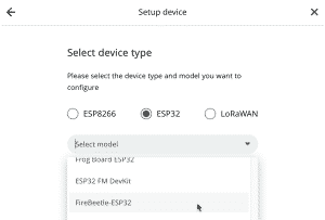
After creating the board, I started testing. I looked at the built-in LED, and the sensors.
Build-in peripherals and the DS18S20 sensor
Keeping in mind the peculiarity with the pin names, I was able to get the build-in LED and the temperature sensor to work without any problems. You can see all the details in the video (above). Below is the code (I have kept the comments):
/*
  Sketch generated by the Arduino IoT Cloud Thing "Firebeetle-ESP32-RGB-LED-Temp"
  https://create.arduino.cc/cloud/things/bd07bedc-c1bc-4da7-86eb-479dd1c58d86

  Arduino IoT Cloud Variables description

  The following variables are automatically generated and updated when changes are made to the Thing

  CloudColor color;
  float temperature;
  bool led;

  Variables which are marked as READ/WRITE in the Cloud Thing will also have functions
  which are called when their values are changed from the Dashboard.
  These functions are generated with the Thing and added at the end of this sketch.
*/
// Documentation, see https://docs.arduino.cc/cloud/iot-cloud/tutorials/technical-reference#cloudcolor
#include "thingProperties.h"

#include <OneWire.h>
#include <FastLED.h>

#define NUM_LEDS 1
#define DATA_PIN 5
#define CLOCK_PIN 13

CRGB leds[NUM_LEDS];

unsigned long previousMillis = 0;        // will store last time LED was updated
const long interval = 5000;
const int DS18S20_Pin = 25; //DS18S20 Signal pin on digital D2/25
OneWire ds(DS18S20_Pin);  // on digital pin 2

void setup() {
  // Initialize serial and wait for port to open:
  Serial.begin(9600);
  // This delay gives the chance to wait for a Serial Monitor without blocking if none is found
  delay(1500);

  // Defined in thingProperties.h
  initProperties();

  // Connect to Arduino IoT Cloud
  ArduinoCloud.begin(ArduinoIoTPreferredConnection);

  /*
     The following function allows you to obtain more information
     related to the state of network and IoT Cloud connection and errors
     the higher number the more granular information you’ll get.
     The default is 0 (only errors).
     Maximum is 4
 */
  setDebugMessageLevel(2);
  ArduinoCloud.printDebugInfo();

  pinMode(2, OUTPUT);

  FastLED.addLeds<NEOPIXEL, DATA_PIN>(leds, NUM_LEDS);  // GRB ordering is assumed
}

void loop() {
  ArduinoCloud.update();
  // Your code here
  unsigned long currentMillis = millis();
  if (currentMillis - previousMillis >= interval) {
    previousMillis = currentMillis;
    temperature = getTemp();
    Serial.print("Temperature = ");
    Serial.print(temperature);
    Serial.println("ºC");
  }

}

/*
  Since Color is READ_WRITE variable, onColorChange() is
  executed every time a new value is received from IoT Cloud.
*/
void onColorChange()  {
  // Add your code here to act upon Color change
  Color colorValues = color.getValue();
  Serial.print(colorValues.hue);
  Serial.print(",");
  Serial.print(colorValues.sat);
  Serial.print(",");
  Serial.print(colorValues.bri);
  Serial.println();

  leds[0] = CHSV( colorValues.hue, colorValues.sat, colorValues.bri);
  FastLED.show();
}
/*
  Since Temperature is READ_WRITE variable, onTemperatureChange() is
  executed every time a new value is received from IoT Cloud.
*/
void onTemperatureChange()  {
  // Add your code here to act upon Temperature change
  temperature = getTemp();
}
/*
  Since Led is READ_WRITE variable, onLedChange() is
  executed every time a new value is received from IoT Cloud.
*/
void onLedChange()  {
  // Add your code here to act upon Led change
  if (led == true)
      digitalWrite(2, HIGH);
    else
      digitalWrite(2, LOW);
}

float getTemp() {
    //returns the temperature from one DS18S20 in DEG Celsius

    byte data[12];
    byte addr[8];

    if ( !ds.search(addr)) {
      //no more sensors on chain, reset search
      Serial.println("no more sensors on chain, reset search!");
      ds.reset_search();
      return -1000;
    }

    if ( OneWire::crc8( addr, 7) != addr[7]) {
      Serial.println("CRC is not valid!");
      return -1000;
    }

    if ( addr[0] != 0x10 && addr[0] != 0x28) {
      Serial.print("Device is not recognized");
      return -1000;
    }

    ds.reset();
    ds.select(addr);
    ds.write(0x44, 1); // start conversion, with parasite power on at the end

    byte present = ds.reset();
    ds.select(addr);
    ds.write(0xBE); // Read Scratchpad


    for (int i = 0; i < 9; i++) { // we need 9 bytes
      data[i] = ds.read();
    }

    ds.reset_search();

    byte MSB = data[1];
    byte LSB = data[0];

    float tempRead = ((MSB << 8) | LSB); //using two's compliment
    float TemperatureSum = tempRead / 16;

    return TemperatureSum;

  }
Most of the code in the example above is generated automatically by the Arduino IoT Cloud editor.
I was able to get the sensor and the LEDs to work using either pin number (i.e. “D2” or “25” for the temperature sensor, and “D9” or “2” for the LED).
Once the code runs on the device, it is easy to create a dashboard. In the dashboard below, I can click on the switch on the left to control the green build-in LED, the colour widget in the middle to set the colour of the RGB LED, and see the temperature in the widget on the right
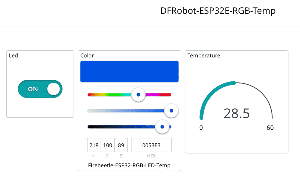
Again, I am glad to report that the build-in board peripherals and the DS18S20 work properly in the Arduino IoT Cloud platform.
The BMI160 test
Unfortunately, the good times ended when I tried to get the BMI160 sensor to work in the Arduino IoT Cloud. I have not successfully gotten the sensor to work in the Arduino IoT Cloud. I checked with DF Robot, and their support agent said, “it’s not supported”.
I suspect some kind of conflict on the I2C bus. If the Gravity breakout had exposed the pins for the SPI, I would have tried that option.
Here’s my (not working) code:
/*
Sketch generated by the Arduino IoT Cloud Thing "Firebeetle 2 BPI160"
https://create.arduino.cc/cloud/things/89ee77d3-6d3f-49fe-bcfd-537fbbaf8403
Arduino IoT Cloud Variables description
The following variables are automatically generated and updated when changes are made to the Thing
float x;
float y;
float z;
Variables which are marked as READ/WRITE in the Cloud Thing will also have functions
which are called when their values are changed from the Dashboard.
These functions are generated with the Thing and added at the end of this sketch.
*/
#include "thingProperties.h"
#include <BMI160Gen.h>
void setup() {
// Initialize serial and wait for port to open:
Serial.begin(9600);
// This delay gives the chance to wait for a Serial Monitor without blocking if none is found
delay(1500);
// Defined in thingProperties.h
initProperties();
// Connect to Arduino IoT Cloud
ArduinoCloud.begin(ArduinoIoTPreferredConnection);
/*
The following function allows you to obtain more information
related to the state of network and IoT Cloud connection and errors
the higher number the more granular information you’ll get.
The default is 0 (only errors).
Maximum is 4
*/
setDebugMessageLevel(2);
ArduinoCloud.printDebugInfo();
Serial.println("Initializing IMU device...");
BMI160.begin(BMI160GenClass::I2C_MODE,0x68);
uint8_t dev_id = BMI160.getDeviceID();
Serial.print("DEVICE ID: ");
Serial.println(dev_id, HEX);
BMI160.setGyroRange(250);
Serial.println("Initializing IMU device...done.");
}
void loop() {
ArduinoCloud.update();
// Your code here
int gxRaw, gyRaw, gzRaw; // raw gyro values
// read raw gyro measurements from device
BMI160.readGyro(gxRaw, gyRaw, gzRaw);
// convert the raw gyro data to degrees/second
x = convertRawGyro(gxRaw);
y = convertRawGyro(gyRaw);
z = convertRawGyro(gzRaw);
// display tab-separated gyro x/y/z values
Serial.print("g:\t");
Serial.print(x);
Serial.print("\t");
Serial.print(y);
Serial.print("\t");
Serial.print(z);
Serial.println();
delay(50);
}
float convertRawGyro(int gRaw) {
// since we are using 250 degrees/seconds range
// -250 maps to a raw value of -32768
// +250 maps to a raw value of 32767
float g = (gRaw * 250.0) / 32768.0;
return g;
}
/*
Since X is READ_WRITE variable, onXChange() is
executed every time a new value is received from IoT Cloud.
*/
void onXChange() {
// Add your code here to act upon X change
}
/*
Since Y is READ_WRITE variable, onYChange() is
executed every time a new value is received from IoT Cloud.
*/
void onYChange() {
// Add your code here to act upon Y change
}
/*
Since Z is READ_WRITE variable, onZChange() is
executed every time a new value is received from IoT Cloud.
*/
void onZChange() {
// Add your code here to act upon Z change
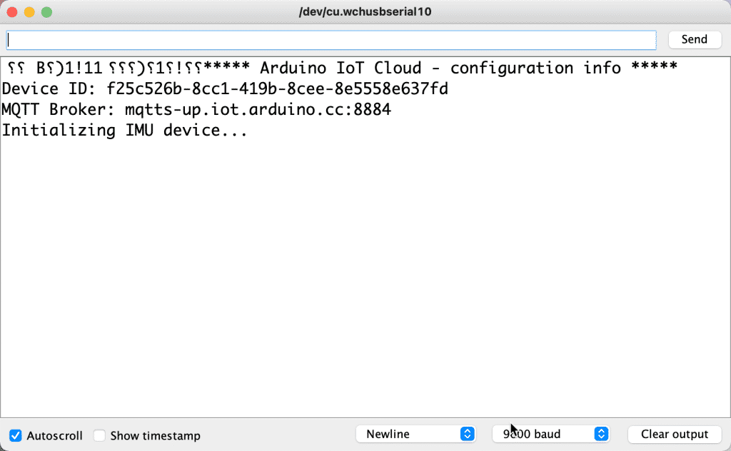
}The sketch is stuck in the setup function, probably in the “BMI160.begin” instruction. I have tried I2C addresses 0x68 and 0x69.
Some might think that a motion sensor in an IoT application might not be advantageous. But I can think of applications where it would be good to determine the position of a gadget, such as whether it is sitting on its side, top or bottom.
I will continue to try to get this to work, and also look for an alternative BMI160 breakout that might expose the SPI interface.
Conclusion
After spending a lot of time with the Firebeetle 2 ESP32-E, this is a high-quality ESP32 board at an excellent price. The on-board peripherals (a green LED, an RGB LED and the side button) are great for getting to know the board out of the box, without additional hardware.
Just as much as I liked the Firebeetle 2 board, I also liked the Firebeetle Expansion shield. Along with the various DF Robot breakout and their specially designed (and colour-coded) connectors and cables, the Firebeetle system allows makers to create gadgets without breadboards or soldering.
Perhaps my next testing project will be to try out the GDI port with one of the compatible displays, such as the Fermion 2.8″ touchscreen or the Fermion 1.54″ LCD.
If you have any ideas about some other DF Robot hardware you’d like me to test, please let me know via the comments below.
If you are interested in learning more about the Arduino IoT Cloud platform, stay tuned for a course announcement in the next few weeks.