
In this experiment, I try out a 1.51″ transparent OLED display. To drive the display, I use a DFRobot Firebeetle ESP32-E and a DFRobot Beetle ESP32-C3 (not at the same time!).
Table of contents
List of hardware, software, resources
Here’s the list of hardware that I used in this experiment:
- Fermion 1.51” OLED Transparent Display with a GDI Breakout
- FireBeetle ESP32-E board.
- Beetle ESP32-C3 board.
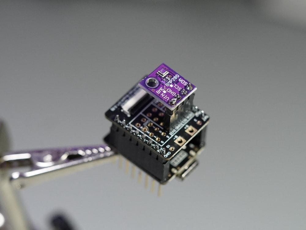
- A generic BME280 sensor, using I2C, to collect some data.
As for software tools and libraries:
- Arduino IDE 2.0 rc9.2 (excellent!), on Mac OS Monterey.
- The U8g2 library for the OLED display from DFRobot (you can use the origial U8g2 library, but the one from DFRobot contains dedicated examples).
- The Adafruit BME280 library.
Other useful resources:
- ESP32-C3 datasheet.
- Beetle ESP32-C3 wiki page.
- FireBeetle ESP32-E wiki page.
- 1.51″ transparent OLED display wiki page.
Wiring – Beetle ESP32-C3
Here is how to connect the display and BME-280 sensor to the Beetle ESP32-C3:
- Solder the female headers on the bottom side of the Beetle, where the branding and model text appears.
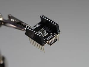
- Solder a 4-pin female header for the sensor on the I2C pins of the Beetle prototyping board.
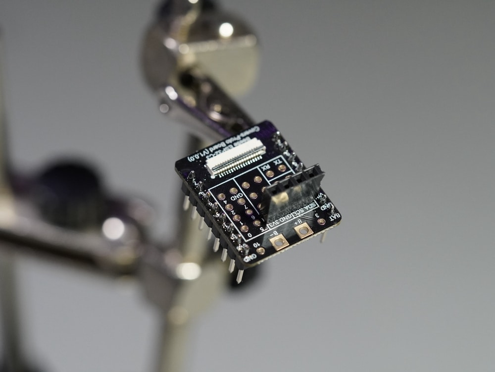
- Solder male headers to the bottom side of the Beetle prototyping board.
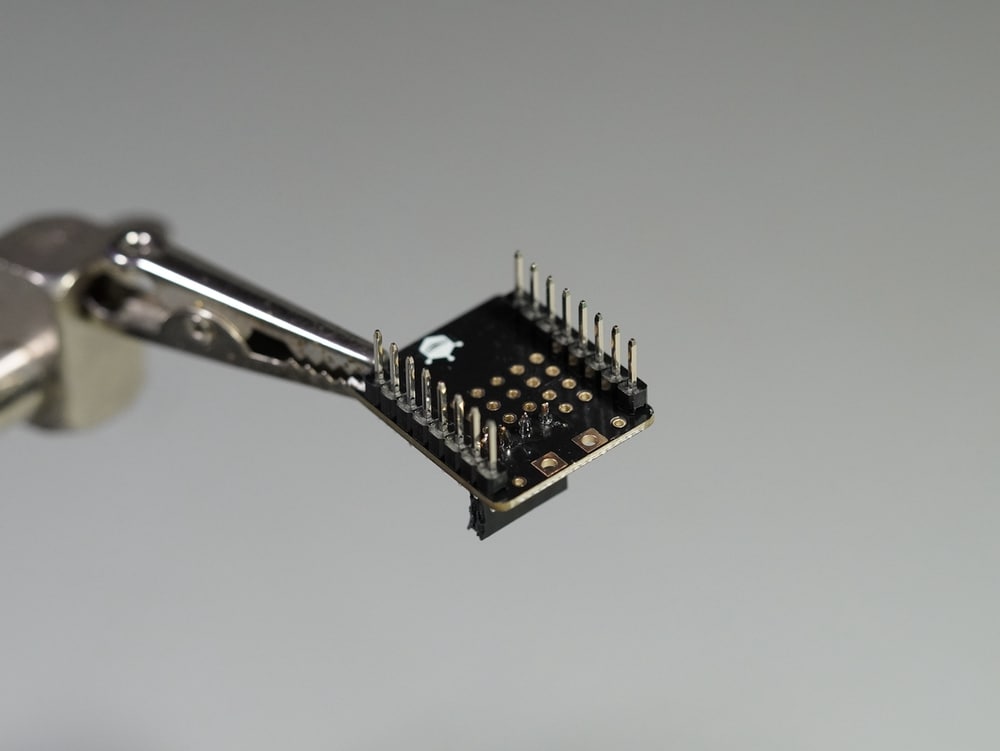
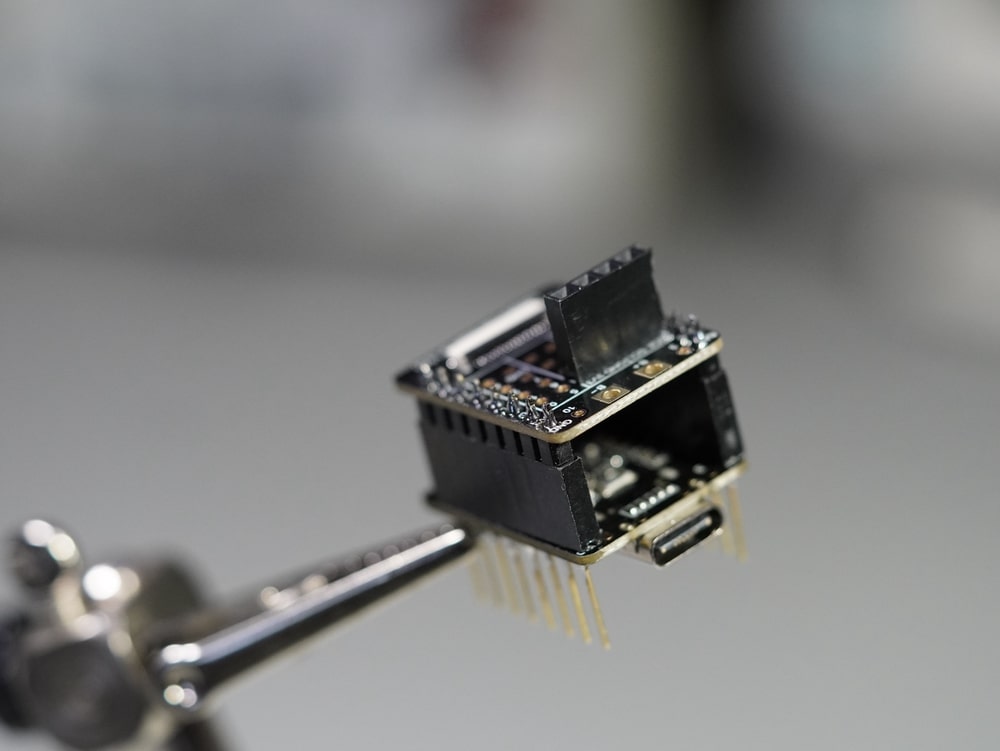
- Attach the Beetle prototyping board to the Beetle board. Take care to match the pins correctly.
- Connect the BME280 sensor to the I2C header on the Beetle prototyping board.
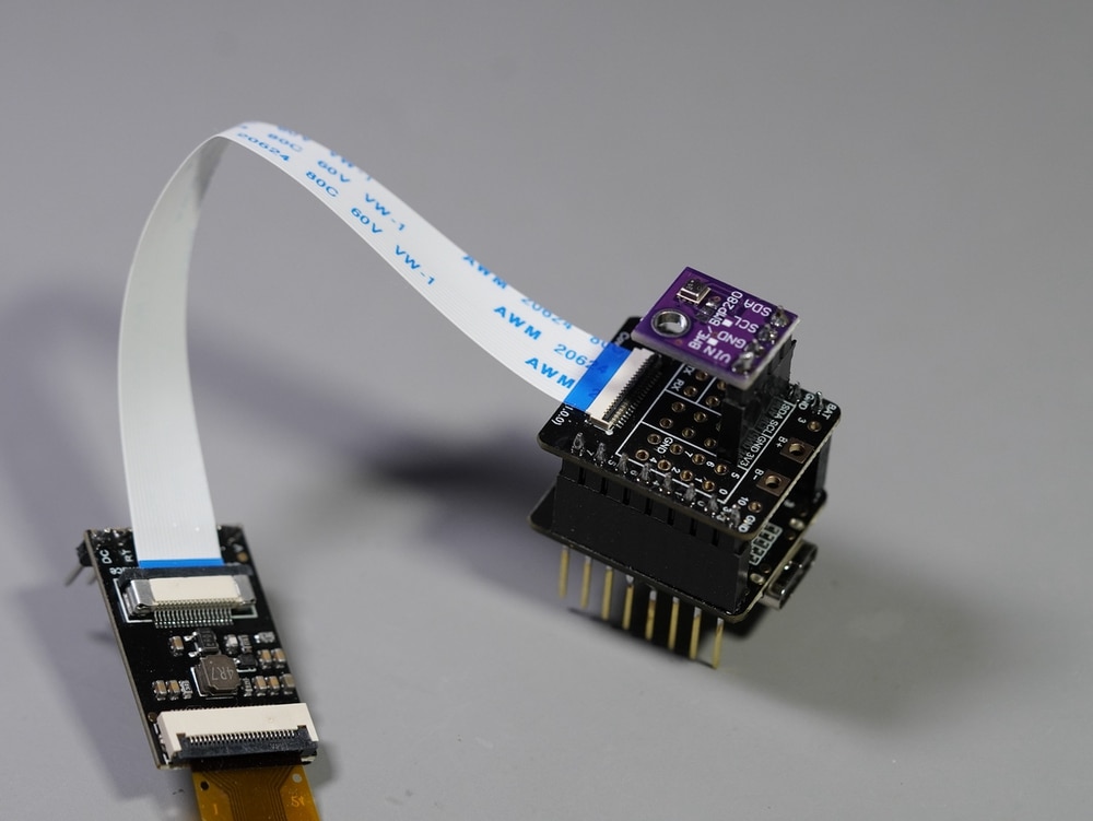
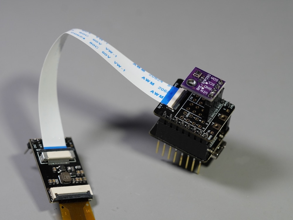
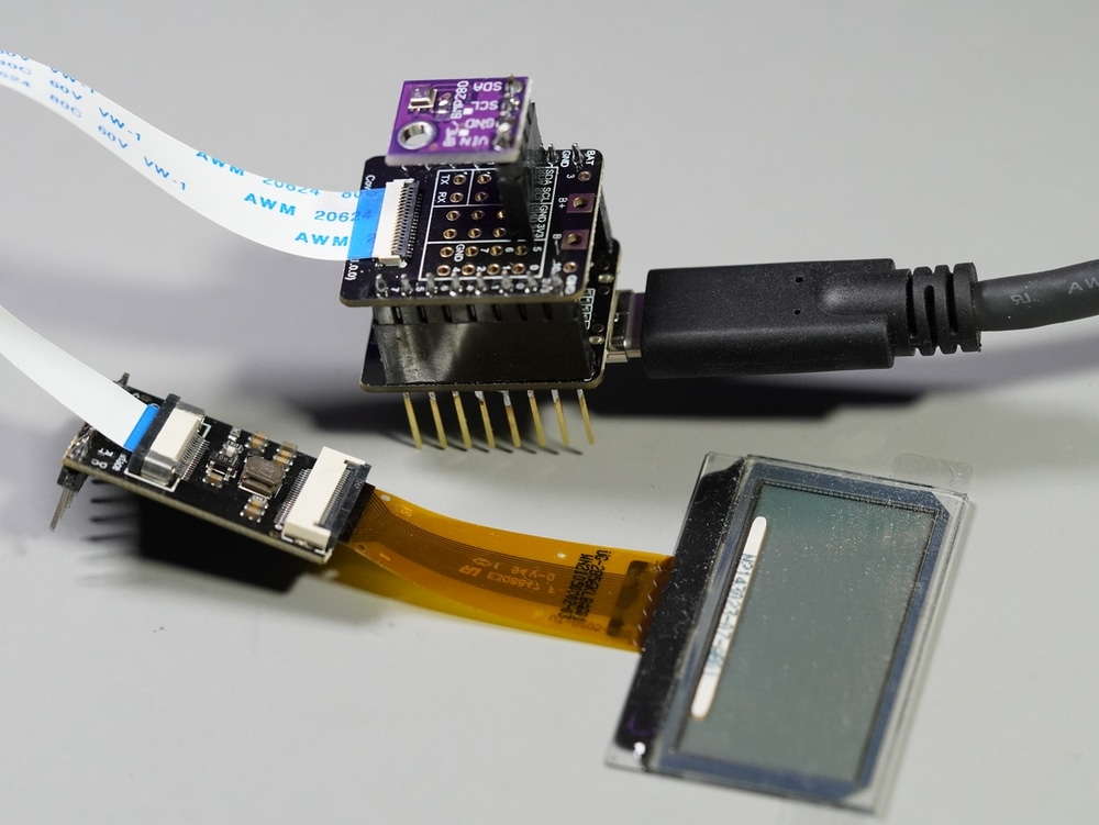
- Display: Attach the display ribbon cable to the matching connector on the display adapter. Take care to gently retract the plastic locking mechanism.
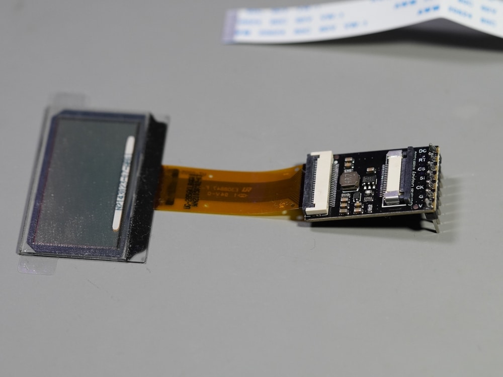
- Display: Attach the flexible ribbon to the display’s adapter GDI connector, blue side up. Take care to gently retract the plastic locking mechanism. In the photos here, you can see the lock open (image 1) and closed (image 2).
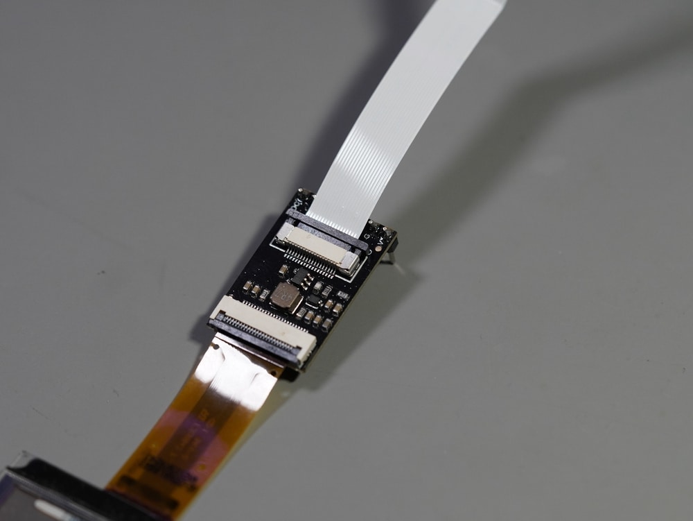
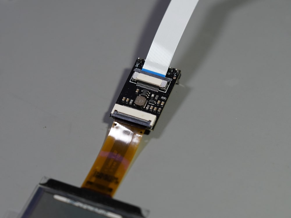
- Display: Attache the other end of the ribbon to the prototyping board GDI connector, blue side up. Take care to gently retract the plastic locking mechanism. In the photos here, you can see the lock open (image 1) and closed (image 2).
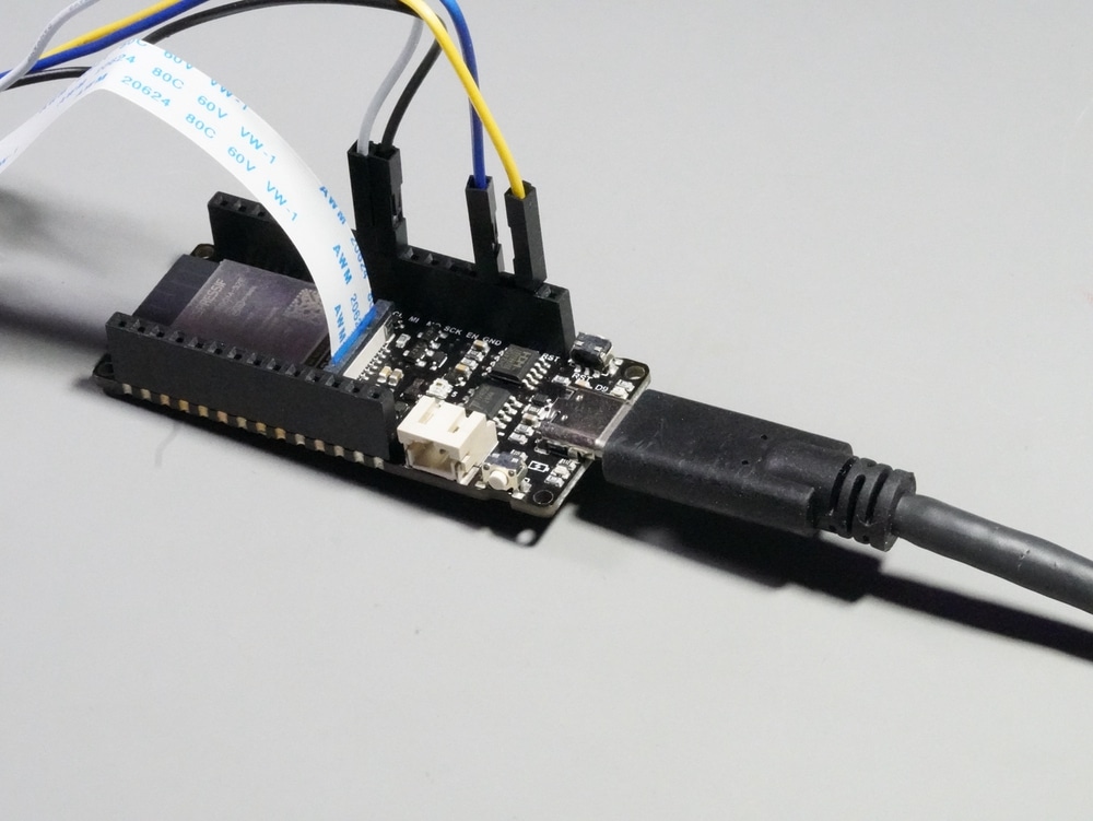
- Review all connections; if all is good, use a USB-C cable to connect the Beetle board to your computer.
Wiring – FireBeetle ESP32-E
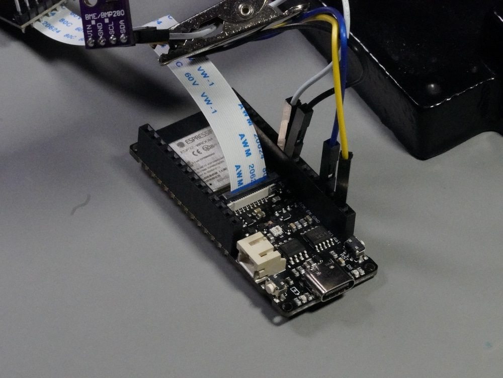
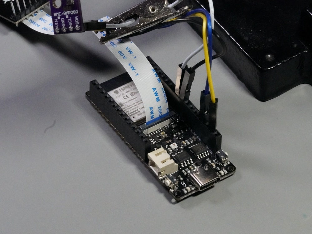
Here is how to connect the display and BME-280 sensor to the FireBeetle ESP32-E:
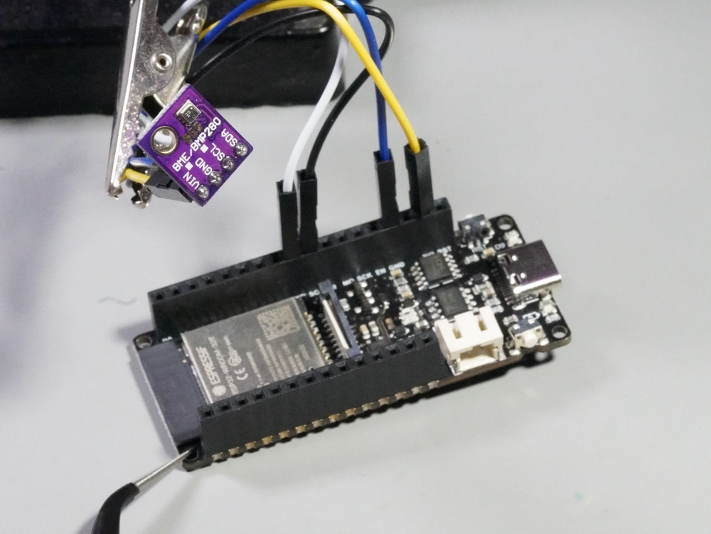
- Use jumper wires to connect the sensor to the board:
- Sensor GND to board GND.
- Sensor Vin to board 3V3.
- Sensor SDA to board GPIO21/SDA.
- Sensor SCL to board GPIO22/SCL.
- Display: Attach the display ribbon cable to the matching connector on the display adapter. Take care to gently retract the plastic locking mechanism.
- Display: Attach the flexible ribbon to the display’s adapter GDI connector, blue side up. Take care to gently retract the plastic locking mechanism. In the photos here, you can see the lock open (image 1) and closed (image 2).
- Display: Attache the other end of the ribbon to the FireBeetle GDI connector, blue side up.Take care to gently retract the plastic locking mechanism. In the photos here, you can see the lock open (image 1) and closed (image 2).
- Review all connections; if all is good, use a USB-C cable to connect the FireBeetle board to your computer.
Example sketch
In my experiment, I used some of the demo sketches available in the U8g2 library provided by DFRobot. In addition, I wrote a small sketch that displays data from the BME280 sensor. This code works on the Firebeetle and on the Beetle boards.
Take care to notice the differences in the GPIO definitions for the display.
To use the display on the Firebeetle, use these definitions:
// these definiations work with the Firebeetle ESP32-E
#define OLED_DC D2.
#define OLED_CS D6
#define OLED_RST D3
To use the display on the Beetle, use these definitions:
// these definiations work with the Beetle ESP32C3
#define OLED_DC  1
#define OLED_CS  7
#define OLED_RST 2
Here is the full sketch listing:
#include <U8g2lib.h>
#include <SPI.h>

#include <Wire.h>
#include <SPI.h>
#include <Adafruit_Sensor.h>
#include <Adafruit_BME280.h>

#define SEALEVELPRESSURE_HPA (1013.25)
Adafruit_BME280 bme;  // I2C

// these definiations work with the Firebeetle ESP32-E
// #define OLED_DC D2.
// #define OLED_CS D6
// #define OLED_RST D3

// these definiations work with the Beetle ESP323C
#define OLED_DC  1
#define OLED_CS  7
#define OLED_RST 2

//U8G2_SSD1309_128X64_NONAME2_1_4W_HW_SPI u8g2(/* rotation=*/U8G2_R0, /* cs=*/OLED_CS, /* dc=*/OLED_DC, /* reset=*/OLED_RST);
U8G2_SSD1309_128X64_NONAME2_1_4W_HW_SPI u8g2(/* rotation=*/U8G2_R2, /* cs=*/OLED_CS, /* dc=*/OLED_DC, /* reset=*/OLED_RST);

void setup() {
  Serial.begin(9600);

  u8g2.begin();
  u8g2.setFontPosTop();

  unsigned status;

  status = bme.begin(0x76);

  if (!status) {
    Serial.println("Could not find a valid BME280 sensor, check wiring, address, sensor ID!");
    Serial.print("SensorID was: 0x");
    Serial.println(bme.sensorID(), 16);
    Serial.print("        ID of 0xFF probably means a bad address, a BMP 180 or BMP 085\n");
    Serial.print("   ID of 0x56-0x58 represents a BMP 280,\n");
    Serial.print("        ID of 0x60 represents a BME 280.\n");
    Serial.print("        ID of 0x61 represents a BME 680.\n");
    while (1) delay(10);
  }
}

void loop() {
  float temp = bme.readTemperature();
  float humi = bme.readHumidity();

  Serial.println();
  Serial.println("======== start print ========");
  Serial.print("temperature (unit Celsius): ");
  Serial.println(temp);
  Serial.print("humidity (unit percent):    ");
  Serial.println(humi);
  Serial.println("========  end print  ========");

  u8g2.firstPage();
  do {
    u8g2.clearBuffer();  // clear the internal memory
    u8g2.setFont(u8g2_font_t0_17b_tr);
    //u8g2.setCursor(0, 5); // Good for U8G2_R0 orientation
    u8g2.setCursor(5, 10);  // Good for U8G2_R2 orientation
    u8g2.print(String(temp, 2));
    u8g2.setFont(u8g2_font_unifont_t_symbols);
    //u8g2.drawUTF8(60, 5, "°"); // Good for U8G2_R0 orientation
    u8g2.drawUTF8(65, 10, "°"); // Good for U8G2_R2 orientation
    u8g2.setFont(u8g2_font_t0_17b_tr);
    //u8g2.setCursor(68, 5); // Good for U8G2_R0 orientation
    u8g2.setCursor(73, 10); // Good for U8G2_R2 orientation
    u8g2.print("C");
    // u8g2.setCursor(0, 20); // Good for U8G2_R0 orientation
    u8g2.setCursor(5, 25); // Good for U8G2_R2 orientation
    u8g2.print(String(humi, 2));
    // u8g2.setCursor(60, 20); // Good for U8G2_R0 orientation
    u8g2.setCursor(65, 25); // Good for U8G2_R2 orientation
    u8g2.print("%");
    u8g2.sendBuffer();
  } while (u8g2.nextPage());
  delay(2000);
}
Learn MicroPython with the ESP32
With this course, you will learn how to use the MicroPython programming language with the ESP32 microcontroller.
MicroPython is a high-level programming language specifically designed for microcontrollers and resource-limited embedded devices. Think of MicroPython as “Python for Microcontrollers”.