
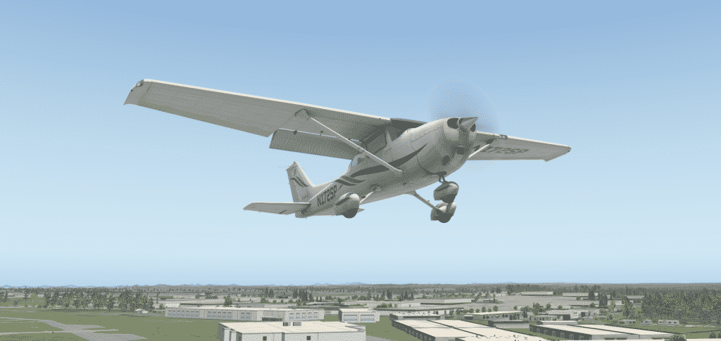
When I’m not working, I often enjoy “flying” a simulated Cessna 172 in a simulated world. For this, I use X-Plane 11. With the help of online courses, I am learning the basics of flight without actually getting into a plane. My (not so secret) hope is that I will eventually do real-world flight training, get a Private Pilot License, and take to the skies in a real plane.
Contents of this article
Until that time, I find that a flight simulator is an excellent tool for learning flight theory and practising all the skills I will need as a private pilot. With the simulator, I don’t have to worry about bad weather, hard landings, crushing my plane, the cost of fuel, or driving three hours to the flight club airport.
I plan to use the simulator to understand the curriculum required for a Private Pilot License, practice some basic skills, and then go for the real thing with an instructor.
One of the first things I had to do after purchasing the flight simulator software was the flight control hardware. People can go totally crazy here, with some going as far as converting their garage into a cockpit. At the very least, I had to look for a yoke, throttle levers and rudder pedals. These items were expensive considering they were relatively simple plastic devices with trivial electronics inside. Their pricing ranged from $50 to $500. Reviews seem to equate those controllers as “garbage” at the cheaper end. At the higher end, quality was premium, but they were impossible to find during the pandemic.
The more I researched the hardware, the more I realized that building my own controllers would be far better than buying them. I like making things, and this would be an opportunity to combine my love of the making and knowledge of Arduino with my desire to learn how to fly.
Building on open source
I did some Googling and found that there were many people out there who were thinking the same way. More than that, they had designed printable flight controllers and posted their CAD plans online. After reviewing many such projects, I settled for Michael Rechtin’s project (see his Youtube video).
Michael’s CAD files contained everything I needed, including the Arduino code for an Arduino Micro. The Arduino Micro contains the Atmega 32U4 MCU with a built-in USB host. This means that I could use an Arduino to take input from buttons and potentiometers and relay the data to a computer via USB. With the help of the Joystick library, the computer would recognize the Arduino as a joystick device.
Making
Once I had collected the CAD files, I started printing them using my Prusa printer. This was my largest print job so far, so I needed a system to keep track of my progress. I used a table, like the one in the resources below (see table “Peter’s 3D printing tracking list). I had to compete for the printer with my kids, so getting everything printed took me almost three weeks.
While the printer was doing its thing, I shopped for the non-printable mechanical and electronics parts. Instead of an Arduino Micro, I used a Pololu A-Star 32U4 Mini LV. This is cheaper and easier to find than the genuine Arduino. Like the Arduino Micro, the A-Star 32U4 Mini has a full-speed USB interface perfect for a custom joystick.
I was able to find (almost) everything else at Aliexpress. You can find my list below (see Parts List), along with the URLs for each item. One item didn’t make it, so I found an alternative on eBay.
Much of my effort in the ordering process was to find items that matched as close as I could to Michael’s specs. A single error in this process could cost me weeks of wasted time, as I would have to re-order from China.
Assembly
Finally, almost two months after starting the project, I had all parts printed and delivered. It was time to do the assembly.
There are no assembly instructions, so I used Michael’s Youtube video. I played the video a few seconds at a time, filling in the many blanks in the process. I have minimal experience working with mechanical parts, so I often had to look at alternative sources of instruction. I tried hard not to break any of the plastic parts. Although I could re-print them, some would need up to 10 hours.

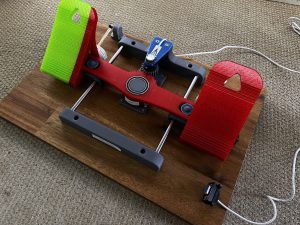
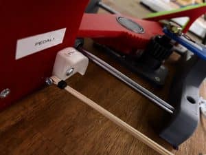
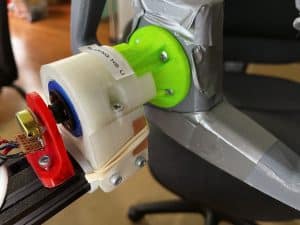
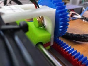
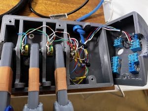
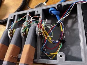
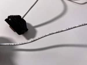
Integrating the pots in the yoke and rudder pedals was reasonably straightforward. I used Ethernet CAT cable for all of the connections between pots, switches and the MCU, and flexible cable to connect the rubber pedal pot to the MCU.
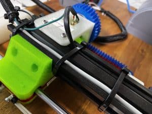
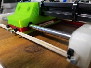
I used an 1800 x 405mm x 18mm timber panel (cut in half along the long edge) to base the yoke + throttle + MCU box and the pedals. I also used anti-skid pads under the panels to keep them from sliding on the desk and floor.
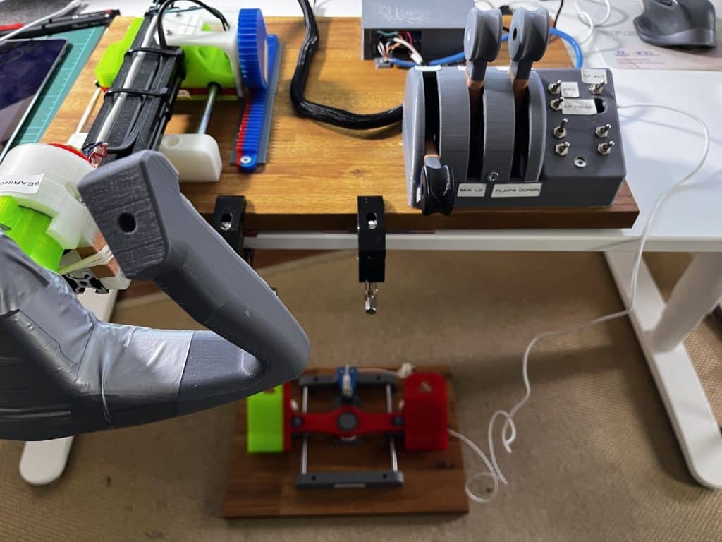
I also used a couple of desk clamps to prevent the yoke assembly from sliding on the desk.
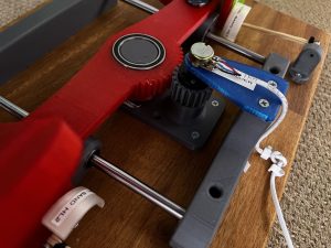
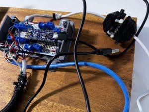
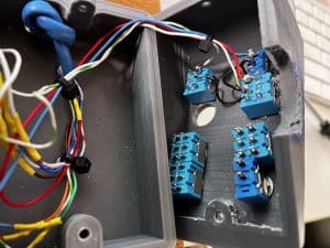
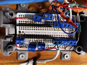
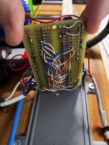
As for the electronics, the key was getting the wires from the pots and switches to the MCU board. I mounted the board on an Adafruit prototyping board using two headers.
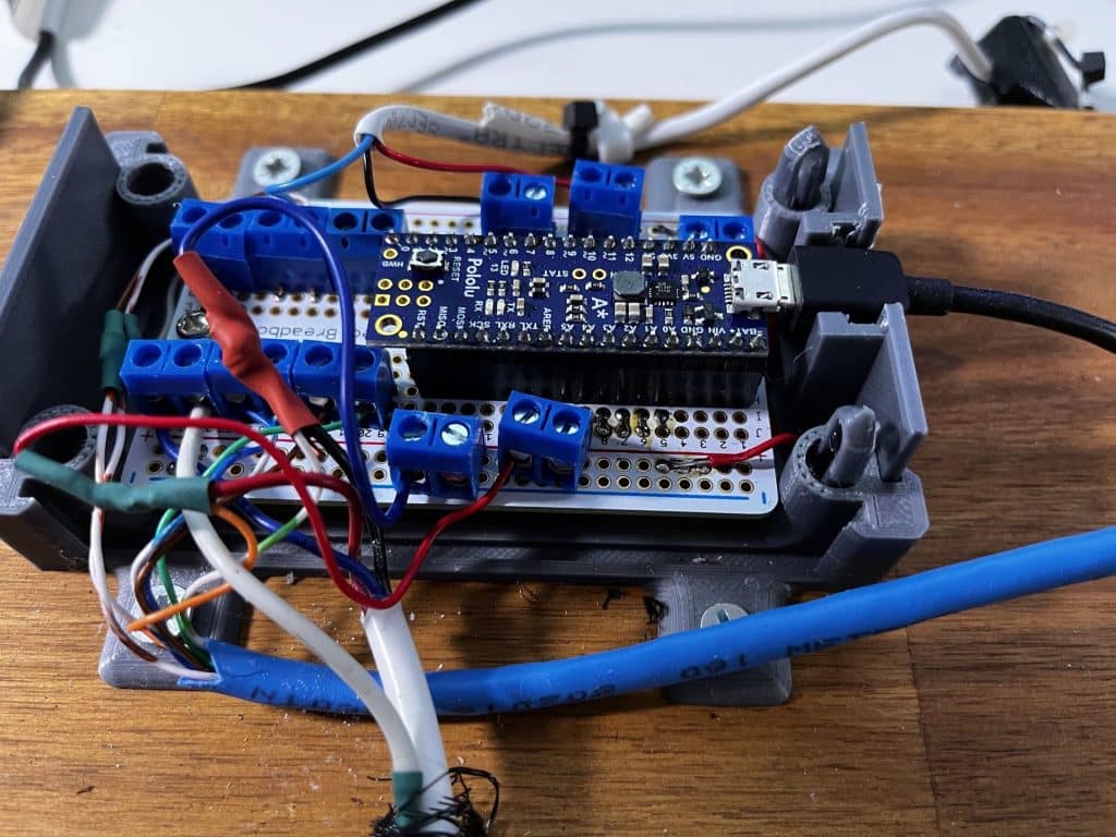
I added 11 double screw terminals to secure the power and signal wires to the board without soldering. As you can see in the photo, the amount of space on the prototyping board is limited, and the wires are very close to each other. I took the time to test each solder for shorts before continuing to the next one.

Programming
Michael has provided an Arduino sketch which I used as a prototype. I made a few modifications to accommodate for my pots and switches, and work with X-Plane.
The key for this sketch is the Joystick library. Once you understand how to use this library, you can create your own custom joystick.
I found that the Arduino sketch was the easiest part of this project.
Testing
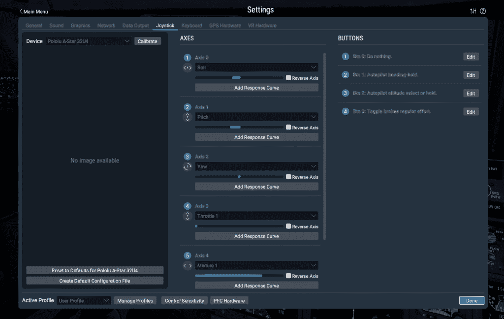
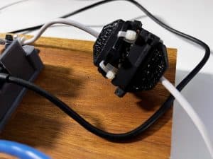
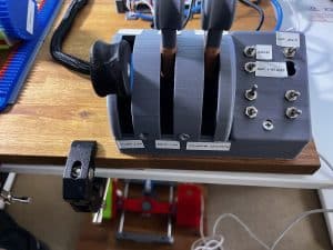
Finally, I completed the mechanical assembly and the programming, and it was time to “fly”. First, I had to set up the flight controls so that X-Plane could take input from them and assign their inputs against the various control surfaces of the simulated plane. So, the rudder pedal pot would control the Cessna’s rudder; the two yoke pots would control the elevators and ailerons. I also assigned the three knobs to the plane’s throttle, fuel mix, flaps, switches to the brakes, autopilot heading, and altitude hold.
X-Planes offers an intuitive settings tool where I can select the joystick device (the Pololu A-Star 32U4, from the device drop-down menu) and then assign the available axes and buttons to a function of the simulated plane.
Flying with my yoke and pedals – impressions
It was a long and challenging build, but I thoroughly enjoyed it. I rarely do an electronics project for fun these days. Because of my focus on my books and courses, every time I make something, I document it by default to convert it into a learning resource for others. This makes “making” feel too much like a job. It slows me down and adds a level of complexity and effort that often takes the fun out of making.
With this project, I decided that I would make it for fun. Michael Rechtin had already done an excellent job creating the CAD files, sketch, and assembly video. Thanks to his work, I would simply enjoy the build and go “flying”.
I enjoyed building it. And it worked.
I was thrilled to experience the smooth performance of my new flight controls in the flight simulator. The yoke and pedals worked perfectly, with no dead zones that users of commercial controllers often report. The X-Plane controller calibration was easy. Once I had everything sorted, I could finally enjoy flying my Cessna.
I now have an appetite to build more 3D printed instruments for my Cessna. Most likely, I will follow the same process, i.e. research for open-source CAD files, and take it from there. I think that the next instrument for printing will be a pitch trim wheel because that’s what I find myself doing most (and I’m using keyboard shortcuts at the moment).
Photographs


Resources
- 3D-printed flight yoke and rudder pedals.
- Michael Rechtin’s assembly video (Youtube).
- Michael Rechtin’s project files (Google Drive) with original CAD files and Arduino code.
- Wiring documentation for the Pololu A-Star 32U4 Mini. The A-Star 32U4 is compatible with the Arduino Micro.
Peter’s 3D printing tracking list
| Part name | Printed | Belongs to… |
|---|---|---|
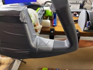
| Bar | Yes | Flight Yoke |
| Yoke (in two parts) | Yes | Flight Yoke |
| Pinion bearing holder | Yes | Flight Yoke |
| Hub Spacer | Yes | Flight Yoke |
| Pot holder roll | Yes | Flight Yoke |
| Pedal 1 | Yes | Rudder Pedal |
| Pedal 2 | Yes | Rudder Pedal |
| Yoke Shaft | Yes | Flight Yoke |
| Linear Bearing Holder Upper | Yes | Flight Yoke |
| Linear Bearing Holder Lower | Yes | Flight Yoke |
| Pot_Holder_Pitch | Yes | Flight Yoke |
| Yoke Pot holder | Yes | Flight Yoke |
| Rack | Yes | Flight Yoke |
| Pinion | Yes | Flight Yoke |
| Pot Holder | Yes | Flight Yoke |
| Rod End 2 | Yes | Flight Yoke |
| Rod End 1 | Yes | Flight Yoke |
| Bearing Housing Upper | Yes | Flight Yoke |
| Bearing Housing Lower | Yes | Flight Yoke |
| Pedal Band Holder 2 | Yes | Rudder Pedal |
| Pedal Band Holder 1 | Yes | Rudder Pedal |
| Rubber Band Holder Back | Yes | Rudder Pedal |
| Pot Holder | Yes | Flight Yoke |
| Rod Holder 1 | Yes | Flight Yoke |
| Rod Holder 2 | Yes | Flight Yoke |
| Pedal Holder 1 | Yes | Flight Yoke |
| Pedal Holder 2 | Yes | Flight Yoke |
| Small gear | Yes | Flight Yoke |
| Gear Mount | Yes | Flight Yoke |
| Lever Knob x 3 | Yes | Control box |
| Lever Low Tolerance Recommended x 3 | Yes | Control box |
| Lever High Tolerance x 3 | No | Control box |
| Lever Cover | No | Control box |
| Button Cover | Yes | Control box |
| Base | Yes | Control box |
Parts list
| Part name | Purchased | Quantity | Source |
|---|---|---|---|
| 8mm x 200mm Steel Rods | Yes | 4 | Aliexpress |
| 30x42x7 Bearing | Yes | 5 | Aliexpress |
| 8mm Linear Bearing | Yes | 4 | Aliexpress |
| V-Slot Bearing Plastic Pulley Wheels | No | 2 |
Aliexpress Amazon.com.au |
| 3/8 x 7/8 Bearing | Yes | 2 | Aliexpress |
| Potentiometer | Yes | 6 | Aliexpress |
| SPST switch on off Snap-in ON/OFF | Yes | 4 | Aliexpress |
| Toggle Switchs 2 Position | Yes | 5 | Aliexpress |
| Potentiometer Hubs | Yes | 2 | Aliexpress |
| Black 500mm Length 2040 V-Slot Aluminum Profile Extrusion Frame for CNC Laser Engraving Machine 3D Printers Camera Slider | Yes | 1 | Aliexpress |
| A-Star 32U4 Mini LV | Yes | 1 | Robotgear |
| DB9 RS232 Male and Female Serial Connectors 9 pin | Yes | 1 | Amazon.com.au |
| Crab Clamp for the desk | Yes | 2 | Amazon.com.au |
Arduino sketch
Tools
Here’s a list of tools I used for the assembly of the flight controllers:
- Soldering iron.
- Multimeter (to check for shorts and continuity).
- Scredriver for driving screws into plastic components.
- Power drill (Duratech) for:
- Drilling holes for wires and switches.
- Sanding 3D printed parts to improve rough surfaces.
- Cutting.