Arduino displays
The 2x16 Liquid Crystal Display (LCD)
In this guide, I'll show you how to incorporate a 2x16 Liquid Crystal Display into your Arduino-based projects. I'll go over the required wiring configurations as well as the sketch.
I recommend connecting the Arduino to the LCD module in
4-bit parallel mode, and I will provide instructions on how to upload the sketch and test the LCD.


Click to play
Introduction
In this article, you’ll learn how to use the 2x16 (two-line, 16-character each) Liquid Crystal Display (LCD). It’s a common type of display used in numerous Arduino-based projects. We’ll use this LCD in our project to display the temperature and humidity readings from the DHT11 sensor. Our course Arduino IoT Environment Monitor Project teaches you how to implement this sensor.
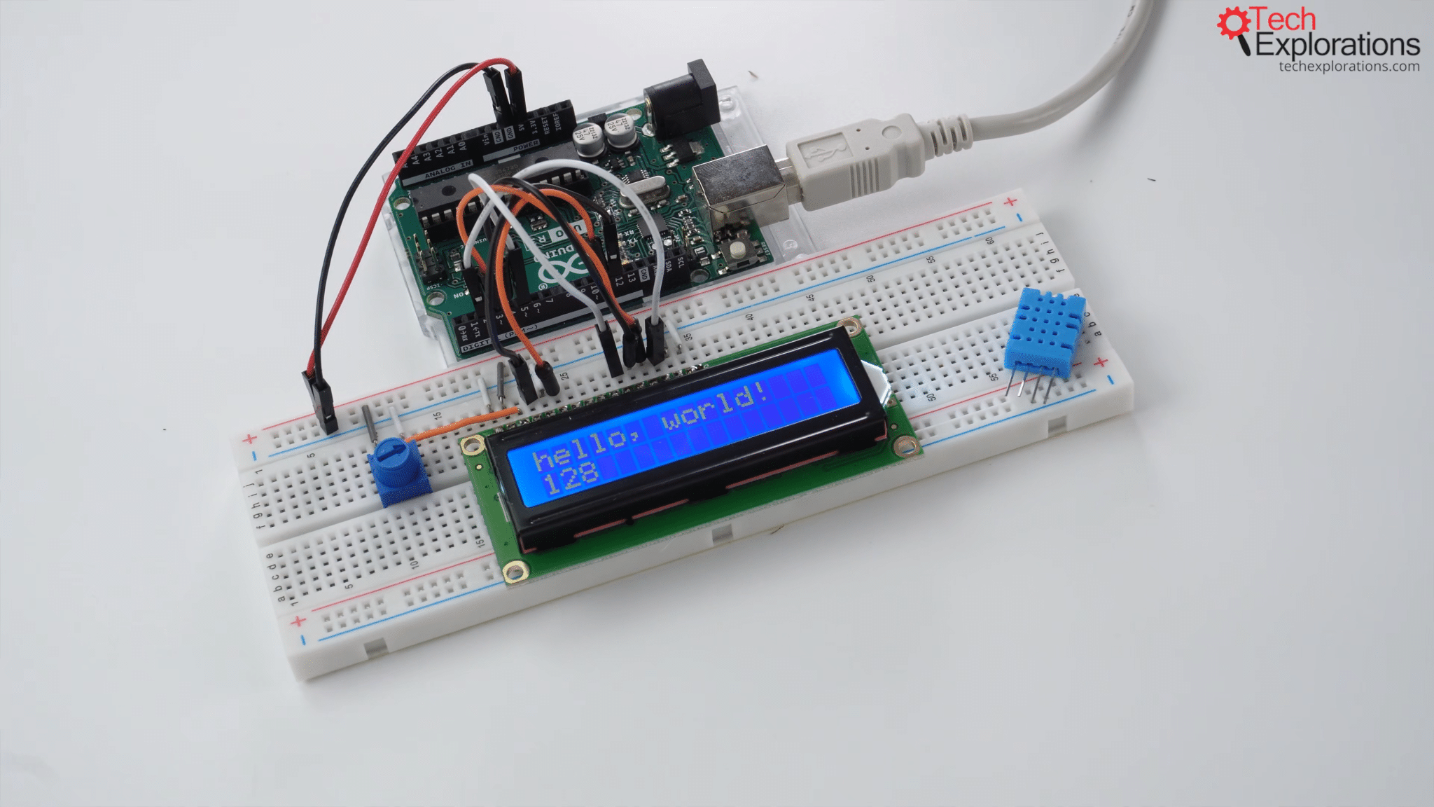
The wired-up 2x16 LCD
As you can see in the image above, I have already wired up the LCD. I’ll explain the setup, and after covering the various methods of wiring, I will discuss the sketch and display some demonstration text on the LCD to make sure everything is set up correctly.
LCD wiring in 4-bit parallel mode
Wiring configurations and the sketch
Let's take a look at the wiring and programming of the 2x16 Liquid Crystal Display. Outlined in this section is the simplest method for connecting this display to the Arduino used in our project. It uses more wires to transmit data from the Arduino to the LCD. However, there is no need for any additional hardware, making this the simplest wiring method.
Overview of displays
I want to take a moment to discuss displays more broadly. I thought it would be helpful to let you know that, as is the case with most electronics, the Arduino is compatible with a wide variety of displays. The Liquid Crystal Display (LCD) is probably the simplest way to show text characters, whether it be numbers, letters, or symbols. The LCD allows for that and more.
In addition to the standard LCD screen, the Arduino can also output data to the user via LEDs, LED alphanumeric displays, and, of course, dot-matrix displays, which excel at displaying graphics with very small, tiny dot pixels.
If you want to learn more about some of those displays, you can refer to my other course, Arduino Step-by-Step: Getting Started, where I have a dedicated section on the liquid crystal display. Also, on Arduino Step-by-Step: Getting Serious I demonstrate various types of displays, including dot-matrix and LED-type displays.
The 2x16 LCD screen
Back to the current topic, if you turn the 2x16 LCD that comes with the 3 in 1 IoT/Smart Car/Learning Kit for Arduino by SunFounder around, it will look like the image below.
The 2x16 LCD included in the 3 in 1 IoT/Smart Car/Learning Kit for Arduino by SunFounder
If you turn the LCD we're going to use around, you can't see any parts other than the pins and bits and pieces that are mounted on the PCB.
The LDC we'll be using in this project
The black module that you see in the image below is an I2C backpack.
The I2C backpack
The I2C backpack converts the 16 pins visible on the base LCD module, to four pins on the converted module, which is the LCD with the black backpack module.
The 16 pins on the base LCD module
The 4 pins on the I2C LCD module
This allows you to simplify the wiring by reducing the number of wires required.
In our example, and I'll explain why in a moment, we'll be using the majority of the LCD module’s back panel pins. When using the black backpack, you only need four pins, two for power and the other two for I2C data and the clock. Therefore, this is the preferred method of connecting the LCD to the Arduino, from a wiring perspective.
The issue here is that using the I2C backpack increases the footprint of your sketch. In my experiments, I found that the Arduino Uno's memory was too low to accommodate both the I2C-enhanced LCD and the other features we require in our sketch. The Arduino Uno's storage and RAM were taxed by the tasks of connecting to the internet and the Blynk platform and reading data from the DHT sensor. After turning on the LCD screen's I2C backpack functionality, the sketch stopped running because it was too much for the Arduino to handle.
Therefore, I used the "standard" 4-bit parallel mode to connect the Arduino to the LCD module. This particular LCD screen supports two parallel modes: 4-bit and 8-bit. If we use the 4-bit mode, we'll need four data pins. And if we use the 8-bit parallel mode, we'll need to use eight data pins.
Wiring
In terms of the wiring, it looks like this:
The Fritzing version of the sketch
The KiCad version of the sketch
The same wiring is shown above from two different design versions. For the left one, I'm using Fritzing, which is more graphical and representative. I'm using a KiCad schematic for the right one.
However, in either case, the green wires are used to transfer data in 4-bit parallel mode. As you can see, I'm using four of them. If I had used 8-bit parallel mode, I would have needed to use four more of those pins as well as four more Arduino pins to make the connection. Obviously, we wouldn't be able to connect anything else because we would have used up nearly all of the Arduino Uno's digital pins.
The 4-bit parallel connection mode
So we'll use a 4-bit parallel connection mode for this LCD. Starting with the data pins, we'll connect them as follows: The rightmost green cable, as seen in the image above, will connect pin D7 on the LCD module to digital pin 2 on the Arduino. Because we are using a four-pin parallel mode connection, after connecting pins 6, 5, and 4, pins 3, 2, 1, and 0 will remain unconnected. The LCD module's four pins will connect to the Arduino's digital pins 2, 3, 4, and 5.
In addition to the data pins, we'll need the reset pin, which will be connected to Arduino digital pin 12. There is also the enable pin, which we’ll connect to digital pin 11 on the Arduino.
Then there's a potentiometer, which is discussed in more detail in the course. We'll use the potentiometer to control the contrast of the LCD and connect it so that 5-volt power is applied to the leftmost pin. The other one on the other side will connect to ground (GND). The middle pin will be connected to the third from the left pin on the LCD module, which is V0. V0 controls the voltage, which in turn controls the contrast of the LCD.
Back on the LCD, on the left side as seen in the image above, there's the VSS pin, which we'll simply connect to ground (GND). The VDD pin power will be connected to 5 volts. The read/write pin is permanently connected to ground.
Finally, on the other side, for the backlit, there is the A (anode) pin, which we’ll connect to the breadboard's 5-volt power rail, and K (cathode) pin, which we’ll connect to the breadboard's ground power rail. The last step is to connect the two power rails to the 5V and GND pins on the Arduino.
The wiring process is now finished.
The Sketch
The sketch is very simple and relies on the LiquidCrystal library, which is already included in the Arduino IDE, so you won’t have to install it separately. If you search in your library manager, you will find the LiquidCrystal library as shown below. You can access the library’s documentation by clicking More info.
The LiquidCrystal library included in the Arduino IDE
I have simplified this sketch so that it only contains the absolutely essential components to drive the screen, but you can find the other available functions in the LiquidCrystal documentation.
LiquidCrystal Functions
For example, I’ll be using the constructor LiquidCrystal() for the liquid crystal, which is shown in this code block:
The code block above also includes begin(), which I’ll use to start the LCD, and print(), which I’ll use to print something out, in this case a bit of text. I’ll also use setCursor() to move the cursor to a specified position on the LCD.
You will get more information about these functions by exploring the documentation in detail. To use setCursor(), for instance, the parameters you would need to specify are the column (col) and the row.
In this example, I specified column zero, which is the leftmost column, and row one, which is the bottom row in the display because we only have two rows. This will move the cursor to the desired location. Following that, we'll print some numbers to represent the number of seconds since the Arduino started.
However, there are other functions that you can explore and experiment with. For example, you can use scrollDisplayLeft() to make text scroll to the left, scrollDisplayRight() to make it scroll to the right, or, if your text is longer than 16 characters, you can use autoscroll() to have it scroll automatically across the screen.
You can either read up on the subject in the documentation or head back to Arduino Step-by-Step: Getting Started to learn more about this LCD, including information on how to use the I2C adapter and communicate with the display using the I2C protocol, which requires far fewer wires.
Sketch uploading and testing
I've assembled the hardware, and the sketch is ready to go, so I'll go ahead and upload it to the Arduino.
Uploading the sketch to the Arduino
So there you go!
hello, world! is displayed in the first row of the LCD
So, hello, world! is the fixed text displayed in the first row of the LCD. In the second row I have a number that counts the seconds since the Arduino began its most recent operation.
I can simply use the potentiometer to adjust the display's contrast, and we can see the effect on the image quality.
Low contrast
High contrast
And that's all there is to the LCD. You now have everything you need to use this liquid crystal display to monitor environment data from the DHT11 sensor.
The liquid crystal display is ready to monitor environment data from the DHT11 sensor

Done with the basics? Looking for more advanced topics?
Arduino Step by Step Getting Serious is our comprehensive Arduino course for people ready to go to the next level.
Learn about Wi-Fi, BLE and radio, motors (servo, DC and stepper motors with various controllers), LCD, OLED and TFT screens with buttons and touch interfaces, control large loads like relays and lights, and much much MUCH more.
Jump to another article
2x16 LCD - 4-bit parallel wiring
LCD screen - I2C wire wiring (soon)
TFT LCD screen
The Seven Segment Display (soon)
128x64 OLED (soon)
Last Updated 2 years ago.
We publish fresh content each week. Read how-to's on Arduino, ESP32, KiCad, Node-RED, drones and more. Listen to interviews. Learn about new tech with our comprehensive reviews. Get discount offers for our courses and books. Interact with our community. One email per week, no spam; unsubscribe at any time
