Arduino displays
TFT LCD Screen
This tutorial will show you how to use the TFT LCD screen shield with an Arduino. I'll go over how to install the necessary library, how to connect the shield to the Arduino, and how to upload example sketches. In addition, we will investigate the functionality of the shield's buttons, and I will suggest exercises to help you better understand the shield's capabilities.
Introduction
The Thin-Film Transistor (TFT) liquid crystal display screen belongs to the LCD family of displays. TFT screens are composed of numerous pixels, which are tiny screen elements that can be turned on and off to create visible markings. These pixels are arranged in rows and columns.
A TFT computer screen can contain many millions of pixels. In small consumer electronics, such as feature phones, there could be several tens or hundreds of thousands of pixels.
If you use a magnifying glass on your computer screen, you will see these tiny pixels. In the color example below, notice that each pixel is actually made up of three: one for green, one for blue, and one for red. The circuitry that controls the screen decides which ones to turn on, how bright they should be, and how long they should stay on. The end result is rich, colorful graphics.
TFT LCD screens are more versatile than LCD screens because there are no restrictions on the things you can display on them. While a humble LCD screen can only display text, a TFT screen allows you to draw anything at all.
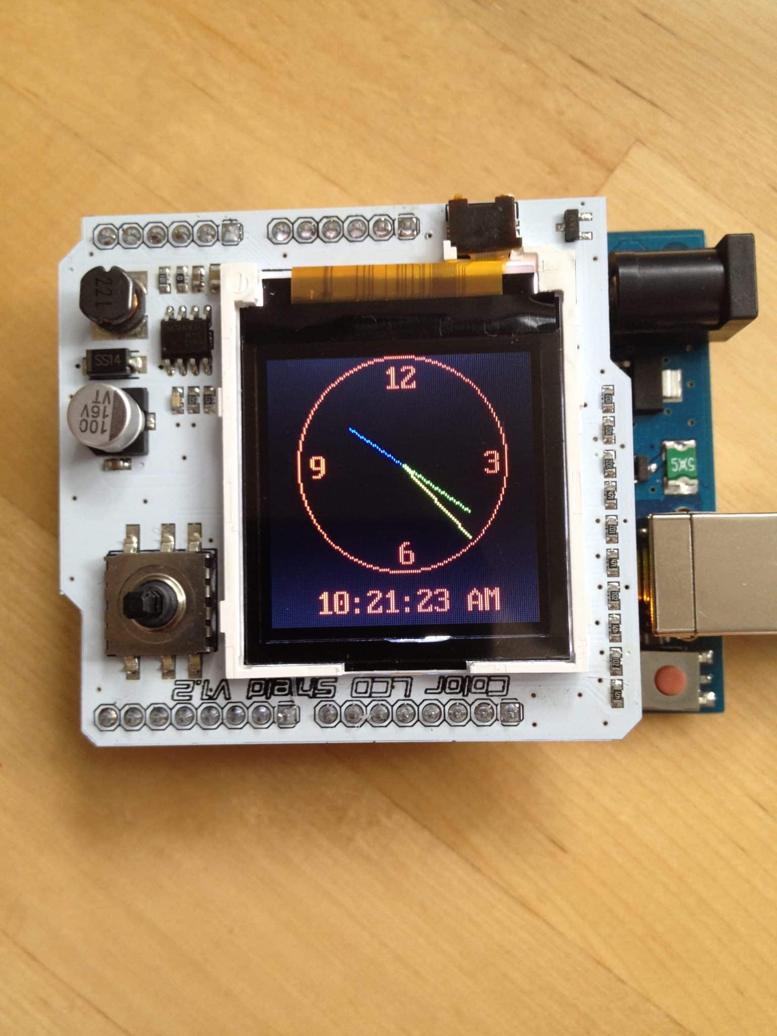
In the example below, I am displaying a clock on my Arduino's TFT display shield. Later in this article, I will provide several examples and show you how to display a clock on the TFT display.

A clock image on a TFT display
TFT screens consist of many pixel elements that require precise control. To achieve this, they come equipped with a screen controller IC as part of the package. Your Arduino communicates with this IC via a serial connection and makes requests for shapes to be drawn on the screen.
However, communicating with the screen controller can be complicated for anyone other than its designers. To simplify this process, libraries have been created. These libraries allow programmers to use simple instructions such as setCircle to draw a circle or setStr to draw a string of text on the screen.
In this article, I am using the first shield we played with in the course Arduino Step by Step Getting Started. A shield is a printed circuit board (PCB) on which several components are mounted, with pin connectors that match exactly those of the Arduino's headers. You simply plug the shield on top of the Arduino, and you are good to go. No wiring or soldering is required, which greatly minimizes the chance of making a mistake or breaking something. This is a good way to experiment with more complicated devices, such as Ethernet adapters, SD card readers, motor controllers, etc.
Demo 1: quick start guide
To get started, you should download and install the library that matches your screen. In my case, I purchased a screen from eBay. After searching on Google, I found that the manufacturer's website had the best matching library.
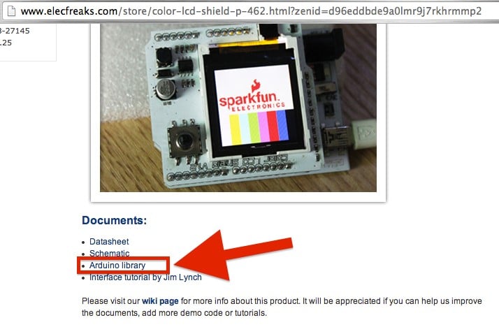
2023 Note: the LCD shield shown may no longer be available in the seller’s website
To make the library available to your Arduino project, and to get access to the example sketches, follow the exact same procedure as you did back in the servo lecture:
1. Download and extract the archive file.
2. After extraction, make sure that the folder name matches exactly the name of the .h file inside it (the folder name should not include the “.h” extension). For this library, the folder name should be “ColorLCDShield”. Capitalization matters.
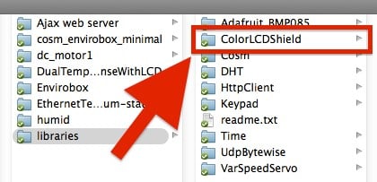
The folder of the ColorLCDShield library
3. Copy the folder to your Arduino’s library folder. If you're not sure where that is, check your Arduino IDE preferences.
4. Restart the Arduino IDE.
To view the ColorLCDScreen examples, click on File > Examples > ColorLCDShield > Examples.
Next, plug the shield onto the Arduino. The headers on the Arduino are designed in a way that makes it difficult to connect the shield incorrectly without causing damage to its pins. Play around with the shield and Arduino to ensure perfect pin alignment, and then apply gentle force to securely connect the two components.
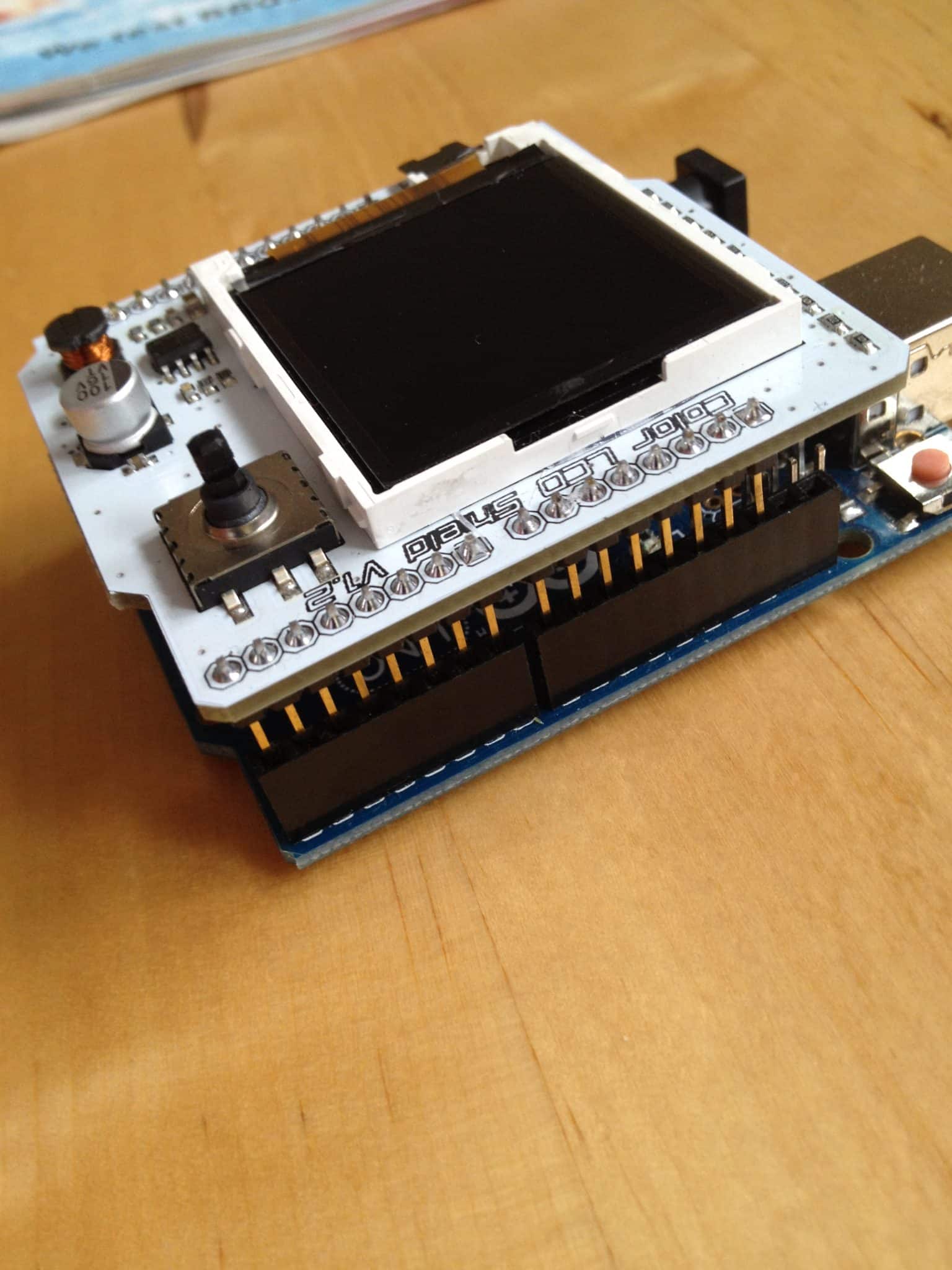
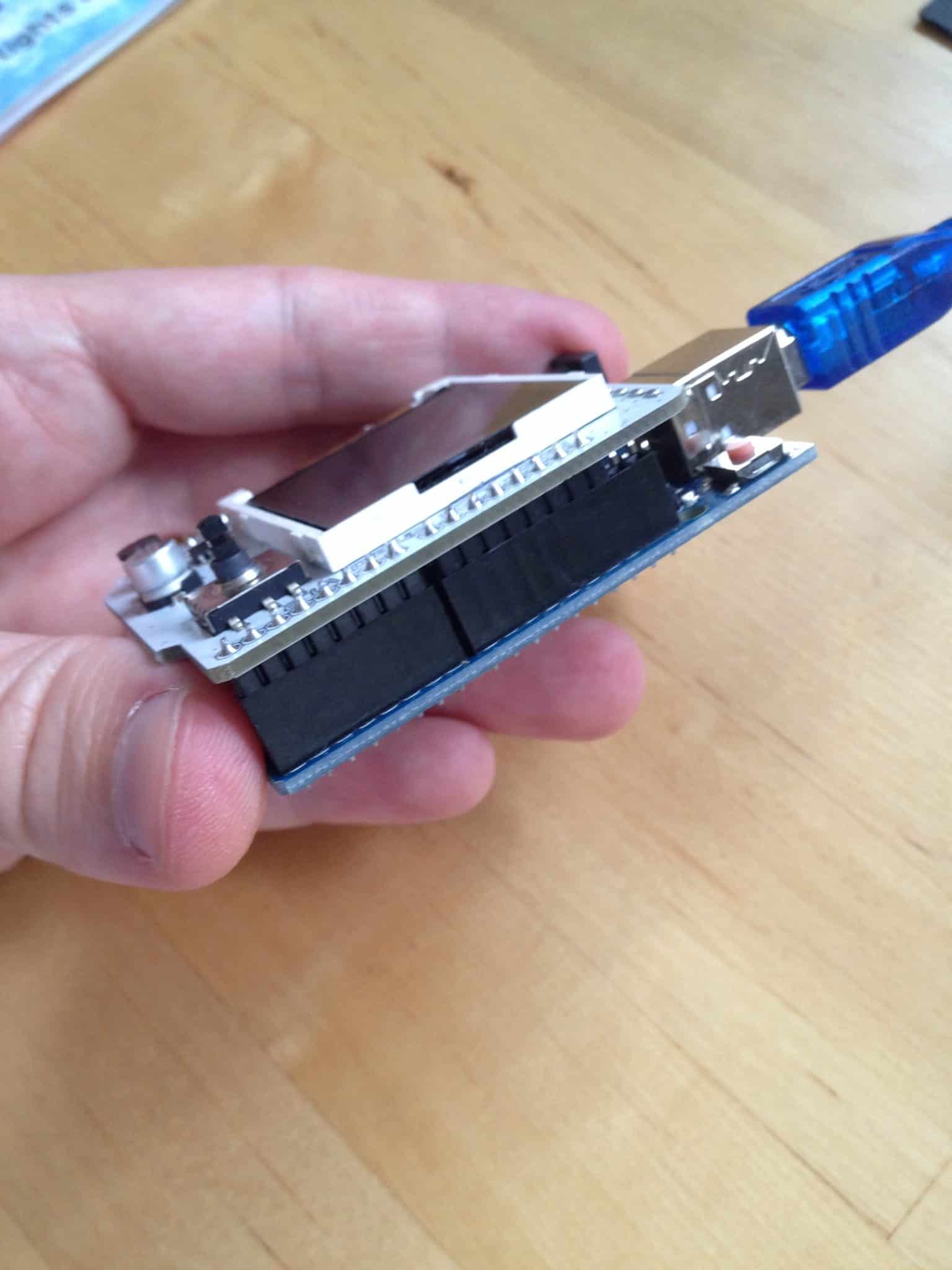
Now that we have the shield installed, let's upload one of the example sketches. Plug the Arduino into your computer, open the Arduino IDE, and navigate to File > Examples > ColorLCDShield > Examples > ChronoLCD_Color.
Below is the sketch. I am showing you only the relevant part at the moment.
Currently, the most important consideration is to determine the type of screen controller used by your screen. Unfortunately, there are no external markings to assist you, and often the manufacturer does not provide any documentation. Therefore, determining the controller type is usually a process of trial and error. The controller will be either PHILLIPS or EPSON. In my case, it happens to be PHILLIPS.
Upload the sketch and check if it works. If it doesn't, edit the line to "EPSON" and see if it fixes the issue.
Wait a few seconds, and a clock should appear on the screen.

A clock image on a TFT display
There's a lot happening in this sketch, so it's better to leave it alone for now. Instead, let's look at something simpler.
Keep everything connected and load this sketch into the IDE:
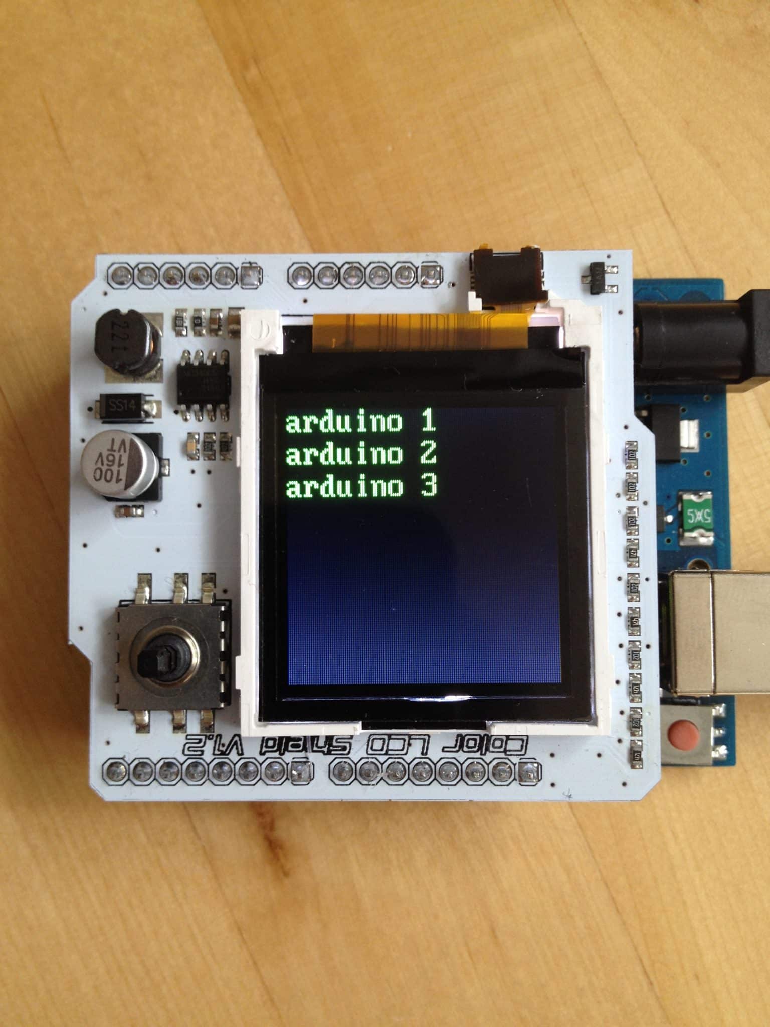
When you upload it, you should see the following on the screen:
The sketch starts by including the LCD library. Next, we define three constants. A constant is simply a name given to a value, so that when we need to use it later, we can refer to it by name. Constants also make code more readable, especially when the values assigned to them are "esoteric" data such as hexadecimal or binary values.
In this sketch, we define the background color as follows:
#define BACKGROUND BLACK
Note that regular lines in the C programming language (which the Arduino language is based on) do not require an ending semicolon (;). In this code, BACKGROUND is a constant with a value of BLACK.
Later in the sketch, there is a reference to this code:
lcd.clear(BACKGROUND);
Here, we are calling the clear function of the lcd object and passing the BACKGROUND constant reference to it. Alternatively, we could have written
lcd.clear(BLACK);
and the result would have been exactly the same. However, consider this: the same code appears in several places within this sketch. If we ever decide to change the background color to pink, we will need to find all references to the clear function and modify its attribute. With a constant reference as an argument, we can simply go to the definition of this reference at the top of the sketch and change BLACK to PINK there. Problem solved!
The next line of interest is:
LCDShield lcd;
We declare an object reference of type LCDShield. We can now use this reference, lcd, to call all of the functions that the LCDShield object class offers.
In the setup() function, we configure digital pin 10 to provide power to the screen's backlight.
pinMode(10, OUTPUT);
analogWrite(10, 1023);
We set the output to maximum brightness by writing a value of 1023 to it. If you want your screen to be dimmer, simply reduce the value written to pin 10.
Next, we inform the lcd object about the type of controller chip it is communicating with:
lcd.init(PHILLIPS);
In my case, my screen uses a PHILLIPS controller. Keep in mind that the alternative is an EPSON controller.
Next, we set the contrast as follows:
lcd.contrast(40);
Adjust this parameter to observe its effect on contrast.
Lastly, these two commands modify the displayed content:
lcd.clear(BACKGROUND);
lcd.setStr("STARTING", 50, 0, C_COLOR, BACKGROUND);
The first line makes everything black because at the beginning of the sketch, we defined the constant BACKGROUND to be black. Next, we write our first string using the setStr function, which takes several parameters.
lcd.setStr([text to show], [start vertical pixel - y], [start horizontal pixel - x], [text color], [background color]);
To write something at the top-left corner of the screen in red with a green background, you would use the following code:
lcd.setStr(“hello”, 0, 0, RED, GREEN);
Simple, isn’t it?
Within the loop() function, we begin by defining an array that contains three pieces of text:
char* Str4[ ] = {"arduino 1","arduino 2","arduino 3"};
Note that the definition is char* Str4[];. The char* indicates to the Arduino that the variable that follows is a pointer (indicated by the * symbol) to a location in its memory where a sequence of characters (indicated by the char data type) are stored. Since a string of text is made up of many characters, we use char. The pointer is then given a name, Str4, and we indicate that it is actually an array by using square brackets after the name: [].
Finally, we initialize a pointer variable to an array of strings using curly brackets, with the 3 strings inside: {"arduino 1", "arduino 2", "arduino 3"}.
We iterate through this array using a for loop. For each item in the array, we call the printString function, which is defined at the end of this sketch.
The printString function requires three parameters: the string to write on the screen, the horizontal (x) start position, and the vertical (y) start position.
void printString(char* toPrint, int x, int y)
You may also remember that void means that a function does not return a value. Instead, it performs an action (like writing text on the screen) and then finishes execution.
In printString, there is a single call to the setStr function, just like we saw in the setup() function earlier.
With this knowledge, you now know how to write text on the screen.
Demo 2: Use the buttons
In this second demo, I will show you how to use the five buttons integrated into the joystick that comes with the shield.
Here is the sketch:
Here’s the first one:
int buttonPins[5] = {A0, A1, A2, A3, A4};
In this code snippet, we declare an array that will contain references to the five Arduino analog pins that convey the status of the five buttons provided by the LCD shield. These buttons are integrated into a mini joystick soldered onto the PCB, next to the screen. Rather than using individually declared variables for the buttons, which we've done in previous sketches, we bundle them in a single array. We then cycle through this array to set them up or to read their values, using and reusing the same code.
That is what we do in the very beginning of the setup() function:
for (int i=0; i<5; i++)
{ pinMode(buttonPins[i], INPUT);
digitalWrite(buttonPins[i], HIGH); }
In this code, we cycle (loop) through the contents of an array that contains the references to the button pins. First, we set them as inputs, and then we turn on their pull-up resistor. This pull-up resistor keeps the voltage of the switch high. When we close the switch by pressing it, the voltage goes down, and the Arduino, guided by the code in the takeInput() function, detects the event.
In the loop() function, we constantly call the takeInput() function and then call the printString function.
Since we have already covered the printString function in Demo 1, let's focus on takeInput() instead.
Here, we individually examine the state of each button. When you push the joystick to the side, one of the buttons creates a connection to Ground, so the digitalRead function returns FALSE. Using the ! operator, we can invert this FALSE value and get TRUE instead. With the if function, we examine this value, and if it turns out to be TRUE, the Arduino will continue within the block and execute any instructions in it, such as clearing the screen and writing text on it.
So, now you know how to use the TFT LCD screen shield with the Arduino. However, there is more to learn, and the best way to do so is through exercises.
Exercise
Take a look at the examples included with the ColorLCDShield library. Can you figure out how to draw a line, a rectangle, and a circle?
Done with the basics? Looking for more advanced topics?
Arduino Step by Step Getting Serious is our comprehensive Arduino course for people ready to go to the next level.
Learn about Wi-Fi, BLE and radio, motors (servo, DC and stepper motors with various controllers), LCD, OLED and TFT screens with buttons and touch interfaces, control large loads like relays and lights, and much much MUCH more.
Jump to another article
2x16 LCD - 4-bit parallel wiring
LCD screen - I2C wire wiring (soon)
TFT LCD screen
The Seven Segment Display (soon)
128x64 OLED (soon)
Last Updated 2 years ago.
We publish fresh content each week. Read how-to's on Arduino, ESP32, KiCad, Node-RED, drones and more. Listen to interviews. Learn about new tech with our comprehensive reviews. Get discount offers for our courses and books. Interact with our community. One email per week, no spam; unsubscribe at any time
