Introduction to the ESP32 guide series
The ESP32 GPIOs
In this lesson, you will learn the basics of the ESP32 GPIOs. You will learn how to recognize the various names we use to refer to them, and some of the functions that they expose.

In this lesson, you will learn the basics of the ESP32 GPIOs. You will learn how to recognize the various names we use to refer to them, and some of the functions that they expose.
You can watch the video, or if you are the “reading” type, you can read the text below.
Which ESP32 pins are exposed via the headers?
Most of the 38 pins of the ESP32 module are broken out in two rows of pins in the ESP32 dev kit, but not all of them.

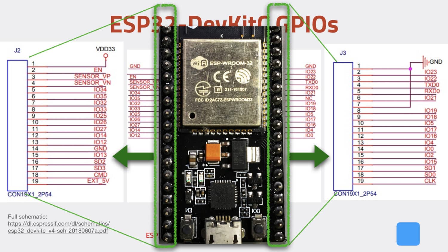
The ESP32 module and Dev Kit pins. Not all ESP32 pins are broken out to the headers.
In the figure shown above, you can see the ESP32 WROOM-32 module positioned at the top of the dev it. Notice that the module has three sides where pins are exposed. The fourth side is where the antenna is placed.
Most of the module pins are broken out to the two headers of the dev kit, the left (J2) and the right (J3) headers. In the same figure, you can see the names of the broken out pins. For example, there are the GPIOs (“General Purpose Input Output” pins), such as “IO43” and “IO17.” Other names are used, too, such as “SENSOR_VP” and “RXD0.”
How do we refer to ESP32 pins?
Almost all pins on the ESP32 are multipurpose, and hence we can use several names that refer to the same physical pin. That depends on what we want to do with a particular pin. In this series and video course, I try to use the GPIO notation exclusively, so I will be using, for example, “GPIO21” to refer to physical pin 42 when I want to use it as the data pin of the I2C interface.
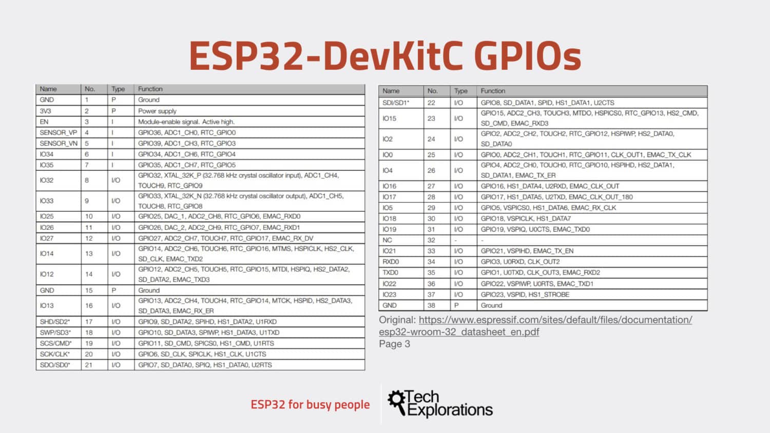
You can find all the information you need about the ESP32 pins and their roles in the WROOM-32 datasheet. In the figure below, I have extracted part of the datasheet that contains the pins I use most frequently.

An extract of the ESP32 datasheet, showing the roles and names of several of its pins.
Notice how each of these pins exposes more than one functions? Apart from the power pins, all of them are multifunction.
Look at an example, such as GPIO34. This corresponds to physical PIN 6. It's an input by default, one of the analog to digital converter channels and it also provides access to the RTC GPIO4.
Try another example, like GPIO2, that is physical pin 24.
This is an input/output pin and has got multiple functionalities: apart from just being GPIO2, it's also an analog to digital converter (ADC) pin channel 2, it exposes a touch sensor, and it's also part of the SPI hardware.
I keep a printout of this Figure handy so I can quickly check on pin roles.
You can download your copy of the high-res version of this figure.
The ESP32 Dev Kit pin map
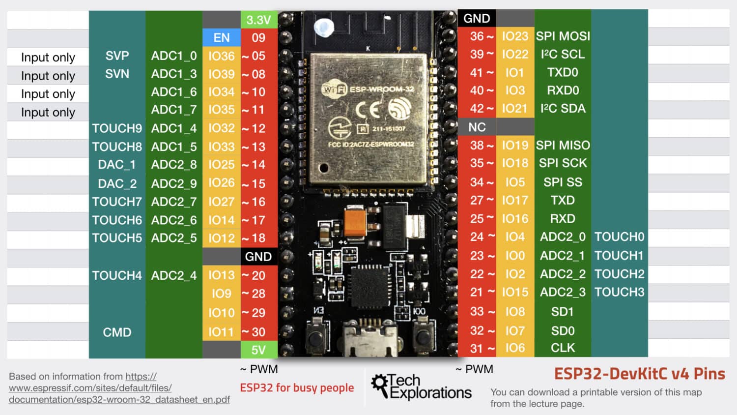
I have also developed the pin map that you can see below. Feel free to download your copy, print it out and keep it handy when you're working with the ESP32 throughout this course.

The Tech Explorations ESP32 Dev Kit v4 pin map, with my compliments 🙂
In this guide and in the video course, I make frequent reference to this map as I find it easier and faster compared to looking up this information in the datasheet. The map contains the pin functions that I use most often.
A quick example. Find GPIO32 in the map. The map shows that this is physical pin 12 in the ESP module, and it give access to one of the touch sensors, and to the analog to digital converter (ADC).
Also, I prefer to refer to pins using their GPIO numbers. In the map, these numbers are contained in the yellow columns.
Datasheet summary table of GPIOs
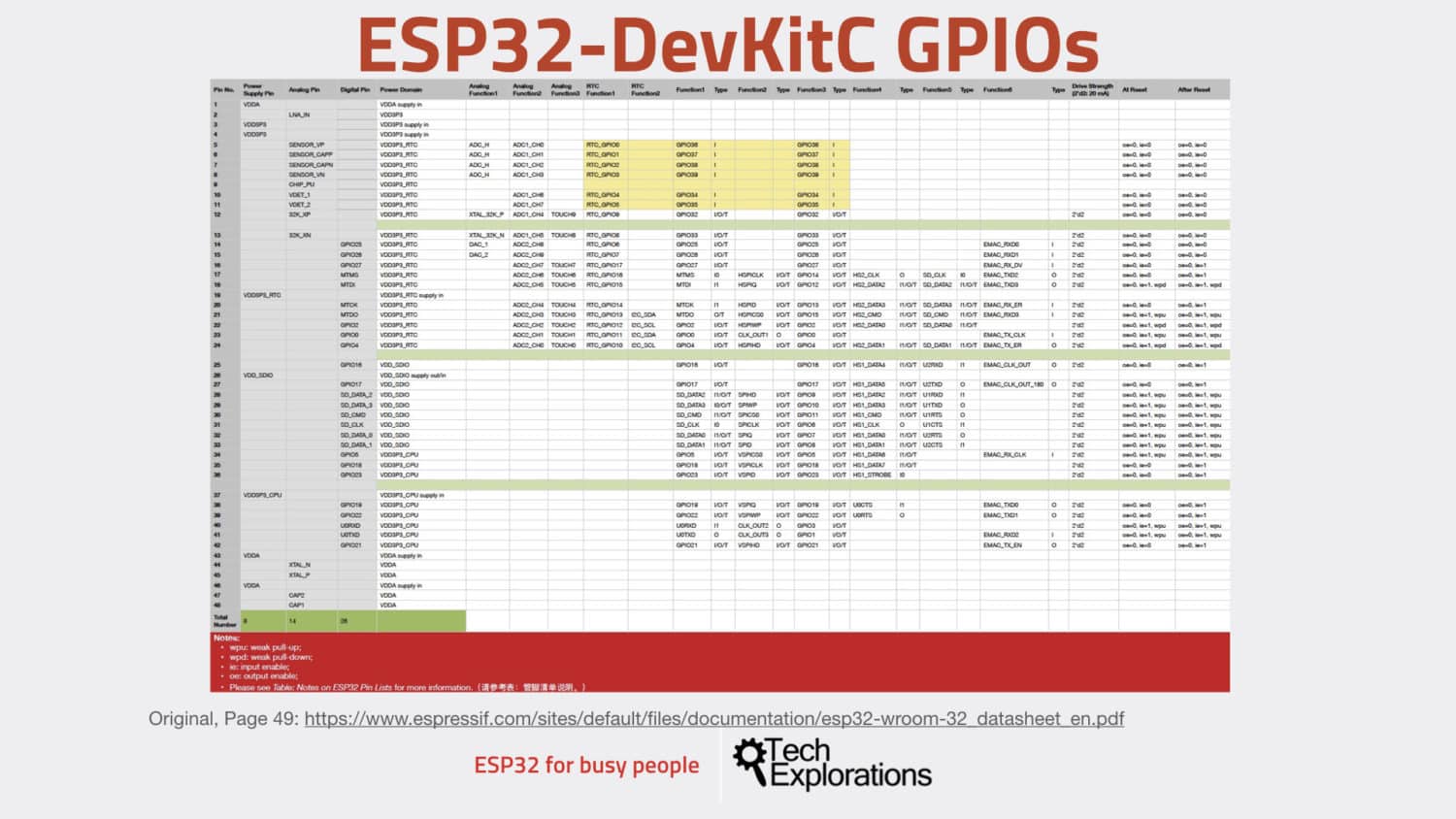
Another document that I use often is this one here:

The GPIO role and naming summary from the ESP32 WROOM32 datasheet.
It comes out of the datasheet and it's a summary of the various functionalities that are exposed at each pin.
Ready for more? Go on to the next lesson and have a look at the ESP32 communications capabilities.
Ready for some serious learning?
Enrol to
ESP32 for Busy People
This is our comprehensive ESP32 course for Arduino Makers.
It's packed with high-quality video, mini-projects, and everything you need to learn Arduino from the ground up.
Just click on the big red button to learn more.
Jump to another article
Lessons
1: The ESP32 module
2: The ESP32 Devkit
3: The ESP32 vs Arduino
4: The ESP32 GPIOs
5: The ESP32 communications
6: The ESP32 devkit power supply
7: Setting up ESP32 in the Arduino IDE on Mac OS
8: Setting up ESP32 in the Arduino IDE on Windows 10
9: Install the drivers CP2102 for the USB bridge chip
10: Digital output LED
11: Digital output PWM
Last Updated 2 years ago.
We publish fresh content each week. Read how-to's on Arduino, ESP32, KiCad, Node-RED, drones and more. Listen to interviews. Learn about new tech with our comprehensive reviews. Get discount offers for our courses and books. Interact with our community. One email per week, no spam; unsubscribe at any time
