Circuits guide series
Pull-Up & Pull-Down Resistors
People that are new to the Arduino and circuit design frequently ask is about pull-up and pull-down resistors. What is the purpose of a pull-up or pull-down resistor, and how does they work?
A question people new to circuit design frequently ask me is about pull-up and pull-down resistors.
What is the purpose of a pull-up or pull-down resistor, and how does it work?
Imagine that you have a switch. One pin is connected to a 5V source, and the other to a logic circuit.
A logic circuit is a component that expects voltage that lies within a specific range and values.
For example, the Arduino Uno expects voltages between 0V and 5V to be applied on its pins. If the pin is digital, then the Arduino Uno will perceive as HIGH any voltage between 5V and 2V, and LOW any voltage between 0V and 0.8V.
Case 1: Vin is determinable
Schematically, you would model a logic circuit connected to a voltage source like this:

The logic circuit has a single input pin on the left side of the blue box, and a single output on the right side.
This pin is connected to a voltage source. The blue wire connects the pin to Vin, a voltage source that is greater than zero (it can also be negative). To depict a voltage source in a schematic, we often use the symbol of a triangle (there are other symbols, but this is a different topic).
If the logic circuit is an Arduino, then Vin could be 5V coming out of a sensor.
In other words, the logic circuit is sensing Vin at its input pin because the wire that connects the pin to ground is uninterrupted.
In the schematic, we denote the voltage sensed by the logic circuit on the input pin as “Vin”.
Case 2: Vin is in-determinable (floating)
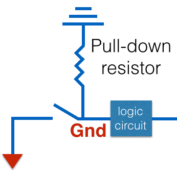
Now, let's add an open switch between ground and the logic circuit’s input pin.
What is the voltage that the logic circuit is sensing on its input pin?

The answer is that we don’t know.
The input pin of the logic circuit is not connected to a voltage source with a specific value.
A term that we use to describe this situation is that the pin is “floating”.
In other words, a pin that is not connected to a specific voltage is said to be floating.
I’ll repeat: the problem here is that the input pin of the logic circuit is not connected to a source of defined value, and logic circuits don't like this!
How do we fix this problem?
Solution: Pull-up or pull-down resistors
Have a look at the next schematic:
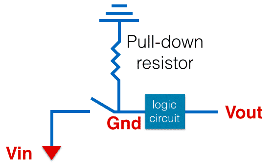
We fix this by using a large resistor (say, 10kΩ or larger) to connect the logic circuit's input pin to ground. In electronics schematics, ground is often depicted with a symbol that consists of three parallel lines, like the one in the example above.
By convention, the voltage level at ground is 0V.
So, when the switch is open, the 0V level from GND is conveyed to the logic circuit’s input pin.
Because of the relatively large resistor between GND and the input pin, the current that flows through the wire is very small. We call this current “leakage current”.
What if we close the switch? Then, we’ll have this:
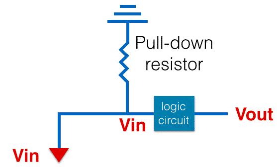
Because the resistor is large, current from Vin will find it much easier to flow through the logic circuit rather than to ground via the resistor.
And, because the connection between Vin and the logic circuit input has negligible resistance, Vin’s value will be transferred to the input of the logic circuit.
Let’s recap: by attaching a pull-down resistor to our circuit, we ensure that the logic circuit’s input will always have a defined value, and will be happy.
You could inverse the circuit and connect the resistor to Vin instead of ground. Now, this resistor would be called “pull-up,” because it would be pulling the input of the logic circuit to Vin (HIGH) when the switch was open.
A pull-up resistor schematic would look like this:
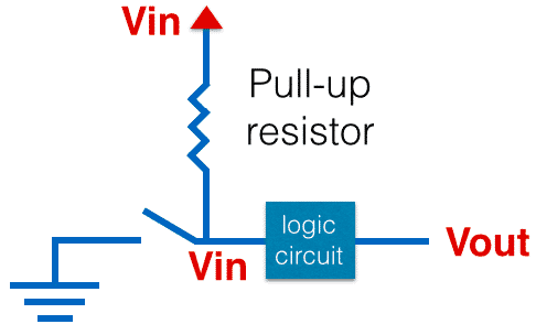
I have just swapped the positive voltage (differential) to the top of the diagram and the ground to the bottom.
When the switch is open, the input of the logic circuit is connected to Vin via the large resistance, so the voltage there is almost Vin.
There will be a tiny current flowing so there will also be a minimal drop in voltage from Vin to the input of the logic circuit, but this is small enough to be able to accept an approximate value at the logic circuit as Vin, which is HIGH.
The Tech Explorations Subscription program
Subscribe and access all of our video courses immediately.
With a catalog of 25+ premium video courses (and growing), this subscription gives you an amazing resource to boost your learning.
Jump to another article
1. Pull-up & pull-down resistors
2. What is a bypass/decoupling capacitor?
3. What is the purpose of the diodes in a keypad circuit?
4. Logic level shifting
5. Why should you use a diode in a relay driver circuit?
6. Why use a voltage divider with a photoresistor?
7. Optoisolator: a simple way to electrically separate parts of a circuit
8. Use MOSFETs to drive large(ish) loads
New to the Arduino?
Arduino Step by Step Getting Started is our most popular course for beginners.
This course is packed with high-quality video, mini-projects, and everything you need to learn Arduino from the ground up. We'll help you get started and at every step with top-notch instruction and our super-helpful course discussion space.
Done with the basics? Looking for more advanced topics?
Arduino Step by Step Getting Serious is our comprehensive Arduino course for people ready to go to the next level.
Learn about Wi-Fi, BLE and radio, motors (servo, DC and stepper motors with various controllers), LCD, OLED and TFT screens with buttons and touch interfaces, control large loads like relays and lights, and much much MUCH more.
Last Updated 1 year ago.
We publish fresh content each week. Read how-to's on Arduino, ESP32, KiCad, Node-RED, drones and more. Listen to interviews. Learn about new tech with our comprehensive reviews. Get discount offers for our courses and books. Interact with our community. One email per week, no spam; unsubscribe at any time

