Arduino peripherals guide series
Using I2C: True digital to analog conversion on the Arduino Uno
The Arduino Uno, with its Atmega328P MCU, does not have true digital to analog conversion capability. For this, we turn to an external device, the PCF8591.

The Arduino Uno, based on the Atmega328p, has no true digital to analog capability. It can only simulate analog signals using pulse width modulation.
Although PWM is sufficient for a lot of applications, there are many more where true digital to analog conversion (DAC) is more appropriate.
For example, making sound in the form of audio effects and simple music, is a typical application of DAC. You can store audio in a "wav" file stored on an SD card (which the Arduino can use), then playback the audio to a speaker. Using PWM is not a good choice for something like this; you need true analog output to reproduce the information in the audio file properly.
To create true analog signals with an Arduino Uno, you can use a DAC module. There are many options in the market.
The NXP PCF8591
A popular DAC module that you can use with your Arduino is the PCF8591 from NXP.
This module contains one 8-bit digital to analog converter and four analog to digital converters, also 8-bit each.
You can connect this device to your Arduino via the I2C bus, using one of 8 possible and configurable addresses. It operates at 5V and 3.3V, so this module is also an excellent choice for 3.3V hosts, like the Arduino Zero and the Raspberry Pi.
Programming the module is easy. Of course, there is a library, but you can also use the raw I2C/TWI interface.
Wiring
Here is the PCF8591 package pin-out, from the datasheet:

Connect the module to your Arduino by doing these connections:
- Device pin 16 (VDD) and 14 (VREF) to Arduino 5V.
- Device pin 13 (AGND) and 12 (EXT) to Arduino GND.
- Device pin 10 (SCL) to Arduino pin A5 (SCL).
- Device pin 9 (SDA) to Arduino pin A4 (SDA).
- Use two 10kΩ resistors to pull up the SCL and SDA pins (connect them to 5V).
- Device pin 8 (Vss), pin 5 (A0), pin 6 (A1) and pin 7 (A2) to GND. This sets the device I2C address to 0x90.
- Connect a 10μF capacitor between 5V and GND.
The analog output pin is device pin 15. This is where you can connect an oscilloscope (so you can see the waveform of the analog output), or an amplified speaker (so you can hear it).
Addressing
What is the address of the device? Because we have grounded the three addressing pins 5, 6, and 7, the address is 144, in decimal, or 90 in hexadecimal. To understand how this works, look at the device datasheet, on page 13. There, you will see this table:

Because bits 3, 2 and 1 of the slave address are 0, the full 8-bit address byte is "10010000". Convert this binary number to decimal, and you'll get 144. In hexadecimal, "0x90".
Sketch
Now, to the sketch. It is as simple as it gets. Our objective is to generate a sawtooth waveform by using a for() loop that sends a single point 8-bit value to the DAC each time:
#include "Wire.h"
void setup()
{
Wire.begin();
}
void loop()
{
for (int i=0; i<256; i++)
{
Wire.beginTransmission(0x90 >> 1);
Wire.write(0x40);
Wire.write(i);
Wire.endTransmission();
}
}
In the example below, inside the for() loop, we transmit three bytes each time:
- Wire.beginTransmission(0x90 >> 1): We start with the device address to enable the slave device and make it listen to the remainder of the communication. Because our Arduino works with 7-bit I2C addresses, but the PCF8591 expects 8 bits, we are doing a right-shift of the slave address by one bit.
-
Wire.write(0x40): We send the control byte which tells the device that we want to enable the analog output. Hexadecimal "0x40" is binary "01000000" (see below for more details about this control byte).
-
Wire.write(i): We send the byte that contains the actual value that we want to convert into an analog voltage on device pin 15.
At the end of the for() loop, we use "Wire.endTransmission();" to finish the current communications session and release the bus.
I2C bus protocol
Let's have a quick look at the structure of the communication between the Arduino and the PCF8591. As I have mentioned in another article, the I2C bus takes care of facilitating the delivery of messages across the bus. What the devices do with the data is up to them. This means that in order to successful exchange data through I2C, you must know the protocol use by the specific devices you are working on.
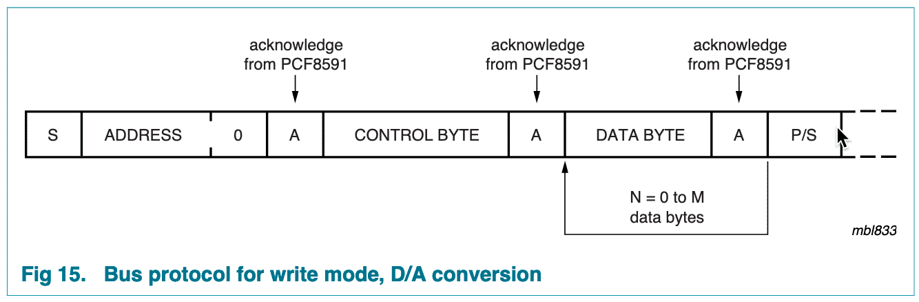
To learn about the I2C protocol of the PCF8591 device, you must refer to its datasheet. In page 13 you will find Figure 15 which depicts the protocol used in write mode. In this example, we are using the write more to "write" an analog value to the analog out pin. It looks like this:

Notice that the protocol expects an address first, followed by a control byte, followed by one or more data bytes. This is exactly the protocol that we have implemented inside the for() loop in our example sketch.
Next, let's focus on the control byte.
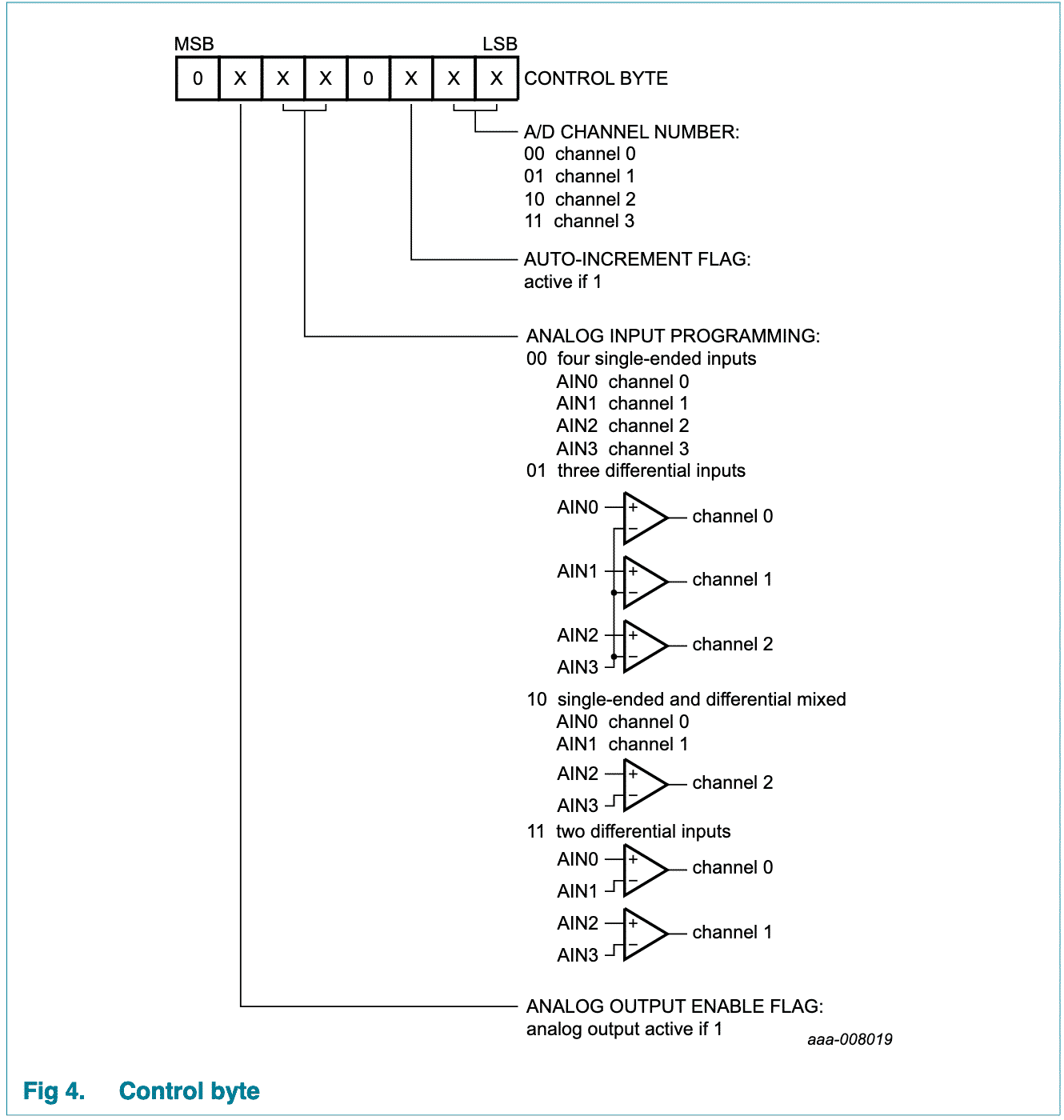
Again, the datasheet is your guide. Go to page 6, where you will find Figure 4:

Remember that we want to write a value to the analog out pin. The second bit from the left controls this function. This bit is the "analog output enable flag". To turn on the analog output pin, we must write a "1" to this bit. The rest of the bits don't matter, so we'll write zeros everywhere else.
Therefore, the binary version of the control byte is "01000000". To save a bit of space in our sketch, we can use the equivalent hexadecimal, which is "0x40".
Either way is correct:
- Wire.write(0x40); // hexadecimal
- Wire.write(B01000000); // binary
- Wire.write(64); // decimal
As you can see, using I2C is very simple as long as you understand the protocol used by the devices involved. The datasheet is your guide, and with relatively small effort you can significantly expand the capabilities of your Arduino.
The NXP PCF8591 can provide you with true digital to analog conversion capabilities for just couple of dollars, which is a fraction of the cost of an Arduino that has this capability built-in.

New to the Arduino?
Arduino Step by Step Getting Started is our most popular course for beginners.
This course is packed with high-quality video, mini-projects, and everything you need to learn Arduino from the ground up. We'll help you get started and at every step with top-notch instruction and our super-helpful course discussion space.
Jump to another article
2. Basics of the TimerOne library
3. How to find device I2C address
4. Getting started with I2C on the Arduino
5. Using I2C: True digital to analog conversion on the Arduino Uno
6. How accurate are thermometer sensors?
7. MCP9808: an accurate thermometer module for your Arduino
8. Getting useful motion data from the MPU-6050 device
9. What to do with unused pins on an Atmega328P or Attiny85?

Done with the basics? Looking for more advanced topics?
Arduino Step by Step Getting Serious is our comprehensive Arduino course for people ready to go to the next level.
Learn about Wi-Fi, BLE and radio, motors (servo, DC and stepper motors with various controllers), LCD, OLED and TFT screens with buttons and touch interfaces, control large loads like relays and lights, and much much MUCH more.
We publish fresh content each week. Read how-to's on Arduino, ESP32, KiCad, Node-RED, drones and more. Listen to interviews. Learn about new tech with our comprehensive reviews. Get discount offers for our courses and books. Interact with our community. One email per week, no spam; unsubscribe at any time