
Stephane Calderoni wrote this article. Only the foreword is mine.
Foreword
Often we think we know something well because it seems simple. For example, an LED only needs a small resistor and a bit of voltage to work, and we’re good.
And a buzzer is a buzzer; plug it into a PWM pin and use the tone library to make some sound.
Ok, that will work, but is it the best way? Can it damage the Arduino or any other microcontroller?
Even though I used buzzers often in my gadgets and courses and never had a damaged microcontroller, these are questions I (sometimes) had in passing but did not attempt to answer.
But Stephane did answer these questions and found some very interesting answers.
Here is how it started:
Steph wrote:
I’m working on a simple Arduino project: reprogramming Simon says game with an Arduino Nano, 4 buttons, 4 LEDs and a passive buzzer.
The programming part is a piece of cake, and that’s not my problem, obviously.
I’m more concerned about the electronic part, in which I’m a beginner with no experience.
I don’t have any technical details about the passive buzzer, which was in a Chinese Arduino kit I ordered 3 years ago. On this user guide, page 68, you can see the only technical data I have about this passive buzzer, which is probably very basic and very common.
The wiring instructions given in this guide, like many online tutorials for that matter, seem to me to be really unwise and silly.
Indeed, connecting the buzzer directly, via its positive electrode, to one of the PWM pins of the microcontroller (an ATmega328P) risks putting an electrical stress on it that could damage it or even destroy it completely. The ATmega328P can handle DC currents of up to 20mA on its input/output pins (although you can push it up to 40mA with PWM pulses for example, but that’s really the limit you should not exceed). And the voltage regulator of the Arduino board can accept up to 200 mA on the Vcc (5V) and GND pins.
And thus, Stephane went out to research the problem. Below is his answer. I wanted to publish this post with Stephane’s permission because it is an excellent example of asking the right question(s) to reach a useful and correct solution.
I have preserved Stephane’s original document (posted on our Makers Club), with only minor edits (a couple of typos).
How to (properly) use a buzzer
In the beginning, I wanted to control a simple passive buzzer with an Arduino Nano board to emit sounds of different tones and make a Simon Says game.
The only passive buzzer I had was from a Chinese Arduino kit I bought 3 years ago. For a long time, I was misled by consulting many websites that claim to explain things to anyone who will listen but make many mistakes that could destroy the Arduino board. First of all, contrary to what many people believe, the buzzers sold in cheap Arduino kits are not high-impedance piezoelectric buzzers but low-impedance magnetic buzzers.
And this point is crucial to consider if you want to protect your Arduino board. Not having any precise information about the characteristics of my buzzer, I measured its impedance with a multimeter and found 15 Ω. This allowed me to research, and I finally stumbled upon the correct datasheet for this buzzer type. Mine is a 16R model.

Magnetic buzzers are nothing more than simple speakers. They contain a coil of conducting wire and small magnets and can be assimilated into an RL circuit. The presence of an inductance means that precautions must be taken to absorb the energy released during the sudden drop in voltage at its terminals.
It is also necessary to consider that the buzzer can enter resonance with external disturbances and deliver a current induced by the coil, which would be reinjected into the circuit. To cut short these effects, we must take the precaution of connecting a diode to the buzzer terminals, which will dissipate this energy.
Here, a simple 1N4148 diode is enough to absorb the current induced by the coil. In the case of a piezoelectric buzzer, conversely, connecting a high-value resistor (1 kΩ) in place of the diode will be necessary to dissipate this energy.
To emit a sound, you have to send a square periodic signal to the buzzer whose frequency corresponds to the pitch of the note you want to play. The Arduino framework provides the tone() function for this. It allows producing a PWM signal with a duty cycle of 50% and at the desired frequency:
tone(pin, frequency, duration_ms)Again, many sites claim that you must connect the buzzer to a microcontroller pin capable of delivering a PWM signal.
But this is not true!
You can join the buzzer to any pin!
However, it is important to consider that, to generate a square periodic signal at a given frequency, the tone() function generates a PWM signal with a duty cycle of 50%. To generate such a signal, it uses the ATmega328P’s Timer2. Therefore, the default microcontroller functions that use this timer are no longer available. Nevertheless, it is Timer2 that generates the default PWM signals delivered by pins D3 and D11.
In other words, these pins can no longer be used as such. They can be used as simple digital pins without the default PWM signals. However, you can use either to send the variable frequency PWM signal generated by the tone() function to the buzzer using Timer2. But you don’t have to. You can choose the pin you like to activate the buzzer. I chose to use pin D12 (which is not a PWM pin).
According to the datasheet of my 16R buzzer, the current going through it should be at most 30 mA. And the digital pins of the ATmega328P can only deliver a continuous current of 20 mA. This limit increases to 40 mA in the case of a pulsed current (applicable to a PWM signal with a 50% duty cycle). Therefore, I could have inserted a simple resistor between pin D12 of the Arduino board and the buzzer to avoid damaging it.
For example, with a 10 Ω resistor, we get a 5 / (10 + 16) = 19.23 mA current. This is acceptable for the microcontroller. But I preferred to use a bipolar transistor to allow me to play with this fascinating component and, at the same time, add protection. The transistor is used here in switching mode: it acts as a switch controlled by a current coming from pin D12. From here on, things get a little more complicated and require some calculations.
The transistor I use here is an NPN S8050 D331, also provided by my Arduino kit. It is appropriate to consider a common emitter wiring to facilitate the determination of the unknowns of the circuit and to ensure that we can quickly saturate the transistor without making it too hot.
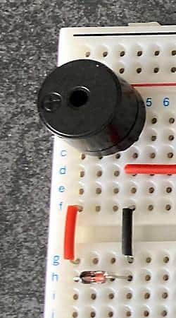
I have represented my electrical wiring in the following diagram. I placed a resistor Rc upstream of the buzzer to limit the current flowing through it (30 mA) and not risk damaging it. This current is led to the collector of the transistor (we will name it Ic).
The datasheet of the transistor specifies that the collector current Ic should not exceed 500 mA. We will be far below this value since we must limit it to 30 mA. To protect the microcontroller and the transistor, I also placed a resistor Rb between pin D12 of the Arduino board and the base of the transistor.
The minimum gain of the transistor given by the datasheet is 50. In other words, the current Ib through Rb to the base of the transistor must be less than Ic / 50 = 500 / 50 = 10 mA. This is mainly acceptable for the ATmega328P. Nevertheless, we will see that we can considerably reduce this value by following the diagram and the resulting equations:
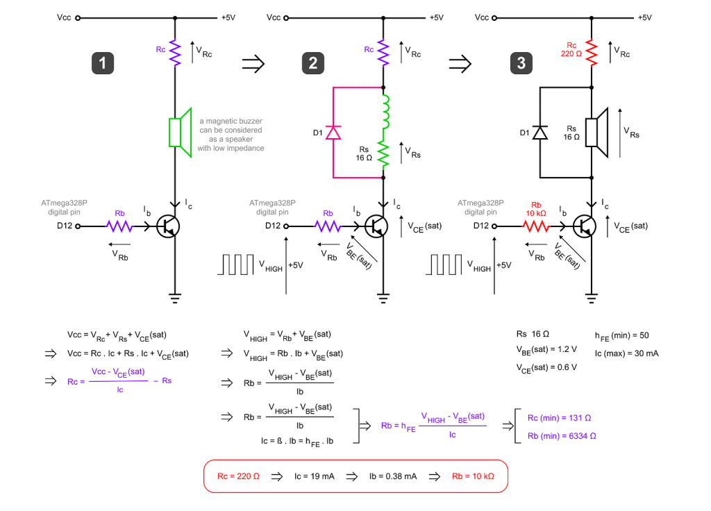
An important note: the average voltage across a pure inductance is necessarily zero in periodic operation.
The values of Rc and Rb represented in purple correspond to the ideal values, which consider the operating limits of the various components. But as a safety measure, we will increase the value of these resistors to stay far below these limits.
For the final wiring, I chose to take the following values (the red ones on my diagram), which guarantee the excellent functioning of the circuit and the protection of all its components:
Rc = 220 Ω and Rb = 10 kΩObviously, the value of Rc (220 Ω) affects the value of the buzzer sound pressure and, thus, the intensity of the resulting sound volume. Of course, we can take lower values to increase the volume.
But we must not go below 131 Ω.
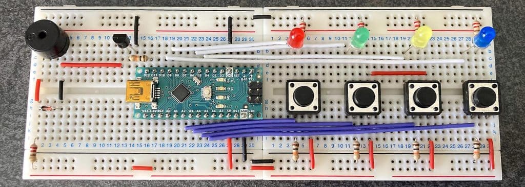
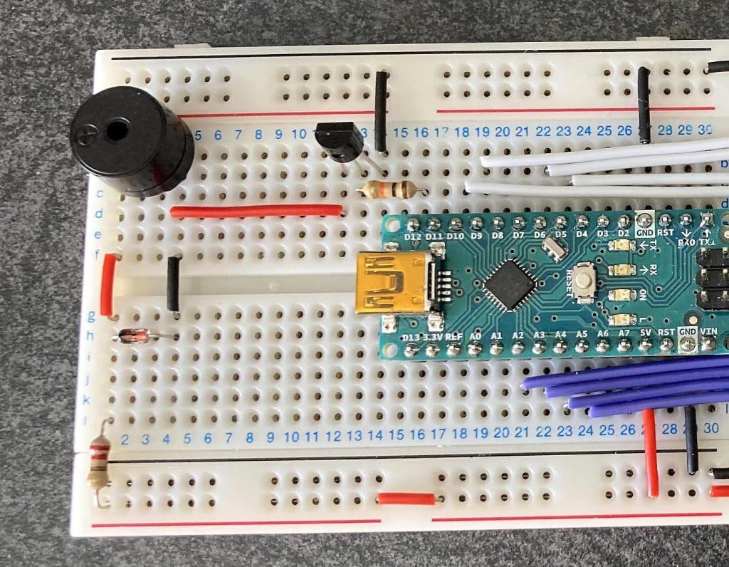
Here is the finalized wiring for my Simon Says game:
And here is the exciting part:
I hope that I have made everything correctly in reasoning and calculation. I count on you, Peter, to correct me if necessary.
I’m glad I was able to solve this problem by myself. It was an excellent exercise, after all. And this post will help your readers realize that we should not trust everything we find online. There are dozens of tutorials on the subject, which are often nonsense…
Cheers,
Steph