Communications
ESP-01S Wi-Fi module: Configuration wiring
This article provides a step-by-step guide to using the ESP8266 Wi-Fi module with the Arduino Uno, highlighting the need for an adapter for breadboard connection. It also details how to configure the module's communication speed and Wi-Fi operation mode, with an alternative option of using a dedicated serial-to-USB adapter.

Introduction to the ESP8266 aka ESP-01S Wi-Fi Module
This article will walk you through the process of using the ESP8266, also known as the ESP-01S Wi-Fi Module. The module can be seen on the device shown below.
The ESP8266 aka ESP-01S Wi-Fi Module
This is a full-fledged microcontroller that, in this implementation, contains special firmware that converts it into an easy-to-use Wi-Fi module.
When connected to the Arduino Uno, the Wi-Fi module uses the serial interface to allow us to write sketches on the Arduino Uno that can communicate with the world via Wi-Fi. Since the Arduino Uno lacks built-in Wi-Fi capabilities, we must rely on external components for this type of functionality.
While there are many methods to add Wi-Fi capabilities to your Arduino Uno, the ESP-01S module is a popular and low-cost option. We will use this module to control our Arduino remote control car via the Wi-Fi interface provided by the ESP-01S, using our mobile phone.
In this article, I will demonstrate how to connect the module and configure it for use with the Arduino Uno's software serial interface.
How to use an adapter to connect the ESP-01S Wi-Fi module to a breadboard
If you flip this module over, you'll notice that it has two rows of four pins.
The flipped ESP-01S Wi-Fi module
The disadvantage of this configuration is that it is not breadboard-friendly. If you connect the ESP-01S to a breadboard, you will notice that the adjacent pins are effectively shorted.
The ESP-01S connected to a breadboard
As a result, if we want to use this module with a breadboard, as shown in this example, we need to use an adapter. The adapter is shown in the image below.
The adapter that will help us connect the ESP-01S to a breadboard without shorting
When you flip the adapter over, you'll see that it has two rows of pins. These rows are breadboard-compatible, which means we can connect them in the configuration shown below without any shorting.
The adapter connected to the breadboard
Then, as demonstrated in the above image, we can use jumper wires on both sides to continue wiring to the Arduino.
Just be cautious. Make sure to plug the module into the adapter as shown in the image on the left, not the one on the right.
This is the correct way to plug the module
This is the wrong way
There is a small arrow pointing down or away from the module to assist you and remind you of the proper way to connect it.
A small arrow showing the way to plug the module into the adapter
This indicates how to properly plug the module into the adapter, as shown in the image below.
The module correctly plugged into the adapter
Another thing to keep in mind is that the SunFounder 3-in-1 Arduino Kit includes two of these adapters. To avoid confusion, I labelled my adapters A and B so that I can have different configurations on each module. When working on a project, I simply look at the appropriate label and say, “Oh, yeah. This is the one I'm using for this experiment.”
Two adapters labelled A and B
I am going to reconnect my adapter to my mini breadboard. I need to be careful with the configuration. I have a red jumper wire that sends 5 volts, and my 5-volt pin is located here.
The 5-volt pin
So this is the correct way to plug it in.
The correct way to connect the adapter to the breadboard
I will plug it in and then attach the module to the adapter.
That's it! Both adapter and module are connected to the breadboard.
Configuring the ESP-01S Wi-Fi Module for Use with the Arduino Uno's Software Serial Interface and a Local Wi-Fi Hotspot
Next, we need to configure the module to use it with our project. I'd like to make two changes to the module's configuration.
- The first modification is to adjust the serial communication speed. The baud rate is set to the default serial communication speed of 115200 bauds. Because we'll be using software serial on the Arduino Uno, I'd like to reduce the serial baud rate of the module to 9600 to improve communication reliability.
- The second modification involves changing the Wi-Fi operation mode to enable this module to connect to a local Wi-Fi hotspot.
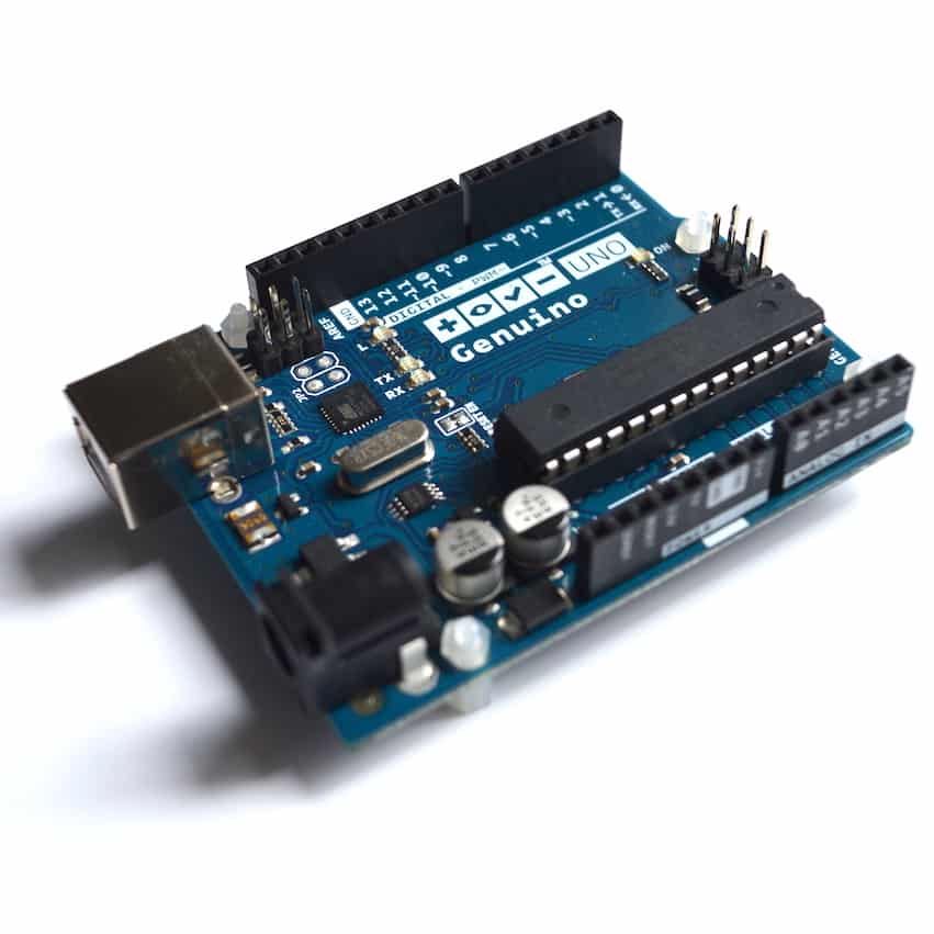
To perform these operations and apply this configuration, we'll use AT commands. For the first part of the process, we'll use the Arduino Uno as a USB-to-serial adapter. This means we'll essentially be using the microcontroller shown in the image below for this purpose. Although it is a microcontroller, it functions as a simple USB-to-serial adapter when operating on the Arduino Uno.
Arduino Uno's microcontroller
The Arduino Uno will also be used to provide power. I've got 5 volts feeding power to the module, essentially powering the Wi-Fi module with the Arduino Uno's power supply.
Alternatively, if you do not want to use your Arduino Uno as a USB-to-serial interface, you can use a dedicated serial-to-USB adapter module such as the FTDI232, which is a very popular USB-to-serial or serial-to-USB adapter.
A dedicated serial-to-USB adapter module...
...the FTDI232!
You need to connect these two RX/TX wires to the RX/TX pins of the FTDI232 module.
The FTDI232 module has two pins that serve as the RX/TX pins. You can connect the two RX/TX wires of the Wi-Fi module to your FTDI module. By doing so, you can replace the Arduino Uno with this device to achieve the same outcome.
Wiring
Now, let's take a quick look at the wiring. To do that, I will borrow the schematic from the SunFounder documentation.
The schematic from the SunFounder documentation at https://docs.sunfounder.com/projects/3in1-kit/en/latest/faq/burn_firmware.html
The wiring is fairly simple. Keep in mind that in this first part of the process, we are using the Arduino Uno as a USB-to-serial adapter.
We have connected the ESP-01 module so that its serial interface is directly connected to the hardware serial interface of the Arduino Uno. While we may switch to software at some point, for this example and this part of the process, we want to configure the Wi-Fi module using the Arduino Uno's hardware serial interface.
To connect the Wi-Fi module to the Arduino Uno, follow these steps:
- Connect the RX pin of the Wi-Fi module (orange wire) to digital pin 0 on the Arduino Uno.
- Connect the TX pin of the Wi-Fi module (blue wire) to digital pin 1 on the Arduino Uno.
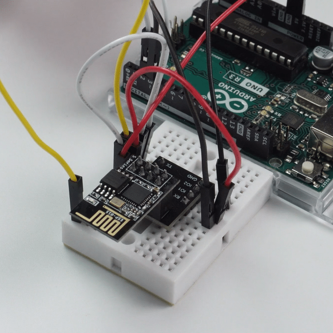
Let's shift our focus to the actual hardware for a moment. Previously, I was working on this hardware using the software serial interface. As you can see in the image below, I have connected my jumper wires to digital pins 2 and 3, which are used to implement software serial.
The jumper wires are connected to digital pins 2 and 3.
I'm going to flip them over to hardware serial.
So, the black wire, which is RX on the module, needs to be connected to digital pin 0. Similarly, TX will go to digital pin 1.
RX is connected to digital pin 0 and TX to digital pin 1.
Regarding the remaining wires, I have connected the ground wire to the ground rail, which is linked to one of the Arduino's ground pins. Additionally, I have connected the IO1 pin to the 3.3-volt output of the adapter. Since the adapter has a built-in voltage regulator, it produces a 3.3-volt output.
To enable the device, I have connected the enable pin to 3.3 volts. Additionally, I've connected the 5-volt pin on the Wi-Fi module adapter to the 5-volt pin on the Arduino Uno for power. As previously mentioned, ground goes to ground.
Lastly, there is a dangling wire to address. This is the yellow jumper wire on the breadboard, which is currently connected to a vacant column on the breadboard. It's not connected to anything and is just floating. This wire will be used to reset the device if it doesn't respond on the Arduino Uno's serial monitor. Simply connect the jumper wire and let it float, without connecting it to anything else unless needed later on.
That concludes the wiring.
Jump to another article
New to the Arduino?
Arduino Step by Step Getting Started is our most popular course for beginners.
This course is packed with high-quality video, mini-projects, and everything you need to learn Arduino from the ground up. We'll help you get started and at every step with top-notch instruction and our super-helpful course discussion space.

Done with the basics? Looking for more advanced topics?
Arduino Step by Step Getting Serious is our comprehensive Arduino course for people ready to go to the next level.
Learn about Wi-Fi, BLE and radio, motors (servo, DC and stepper motors with various controllers), LCD, OLED and TFT screens with buttons and touch interfaces, control large loads like relays and lights, and much much MUCH more.
Last Updated 2 years ago.
We publish fresh content each week. Read how-to's on Arduino, ESP32, KiCad, Node-RED, drones and more. Listen to interviews. Learn about new tech with our comprehensive reviews. Get discount offers for our courses and books. Interact with our community. One email per week, no spam; unsubscribe at any time

