Introduction to the ESP32 guide series
The ESP32 module
In this lesson, you will learn about the ESP32 module that powers the development kit that I am using in this series of lessons, and the video course.
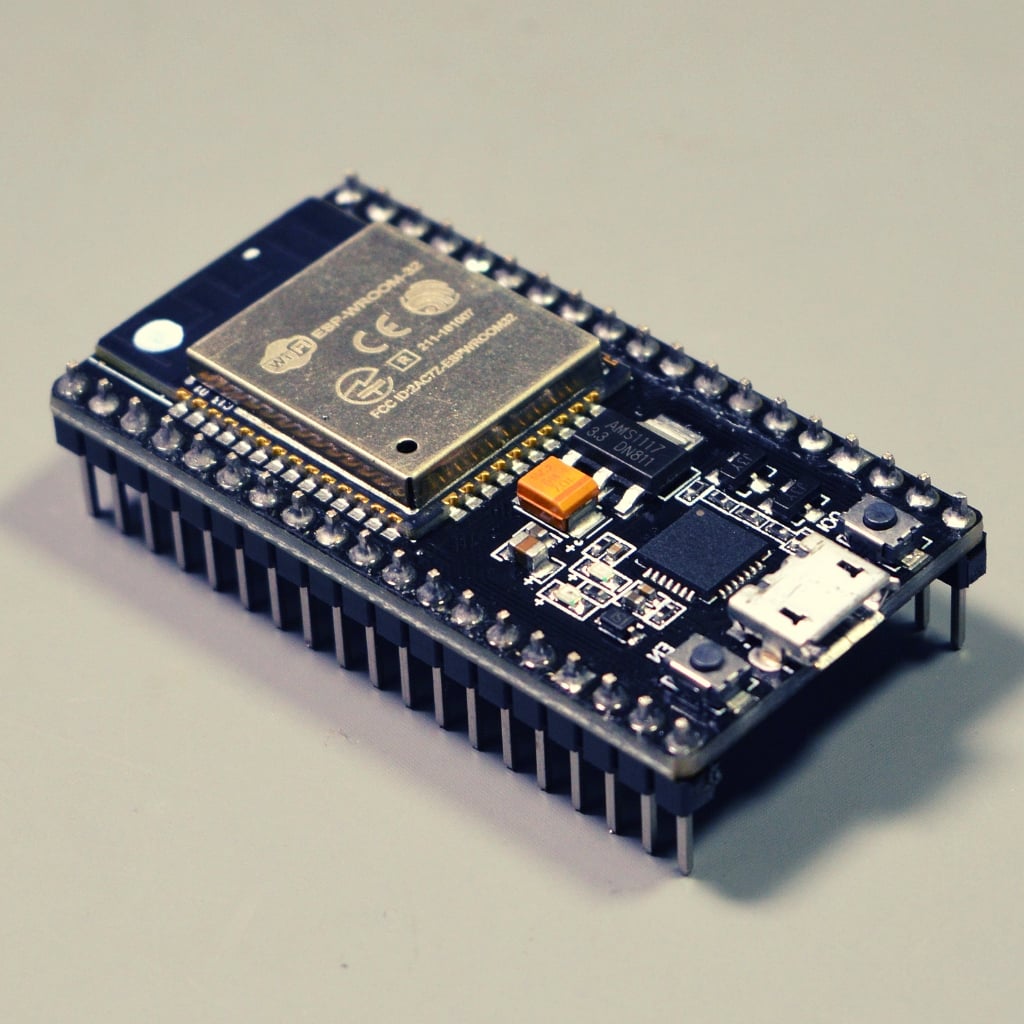
In this lesson, you will learn about the ESP32 module that powers the development kit that I am using in this series of lessons, and the video course.
You can watch the video, or if you are the “reading” type, you can read the text below.
The ESP32 WROOM32 module
In the photo below, the ESP32 module is indicated by the arrow, and it dominates the surface of the development kit. There are several variants of the ESP32 module (more about this below). The once used in the ESP32 DevKit v4 that I will be using in these lessons and course is the WROOM32.
In general, keep in mind that “ESP32” is a generic reference name. We use it to refer to all the ESP32 module models and even the dev kits. It’s a bit like saying “Arduino,” meaning the Arduino family of boards, not a specific board.
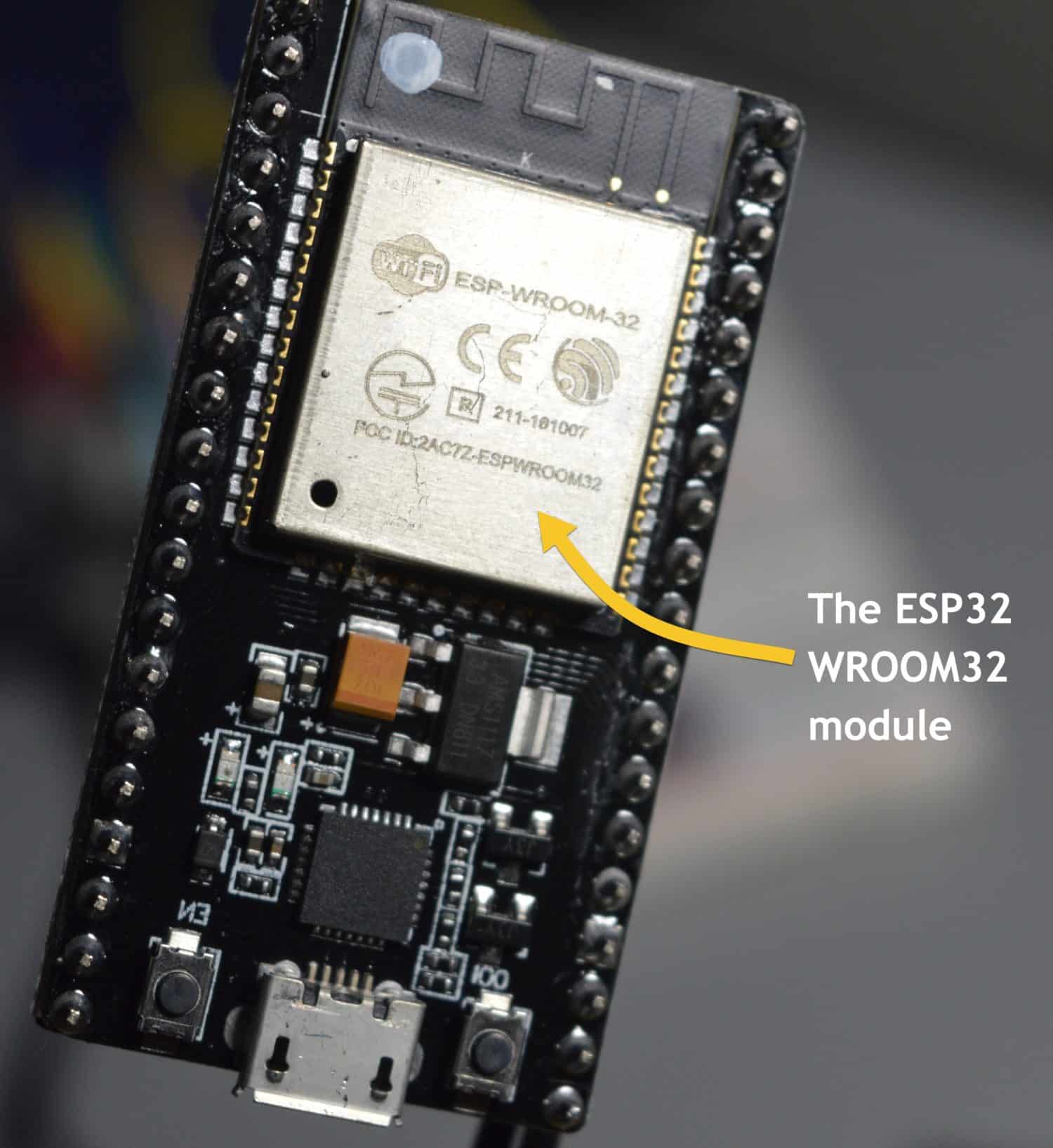
The ESP32 DevKit v4 contains the ESP32 WROOM32 module.
Drilling further into the module, we learn that the WROOM32 module contains the ESP32 D0WDQ6 microcontroller chip.
There’s also another variant, the ESP32 WROOM32D, which contains a slightly different chip that powers it, and there’s also the WROVER modules, such as the ESP32 WROVER-IB which also contains at ESP32 D0WD chip but with additional memory, and many many more.
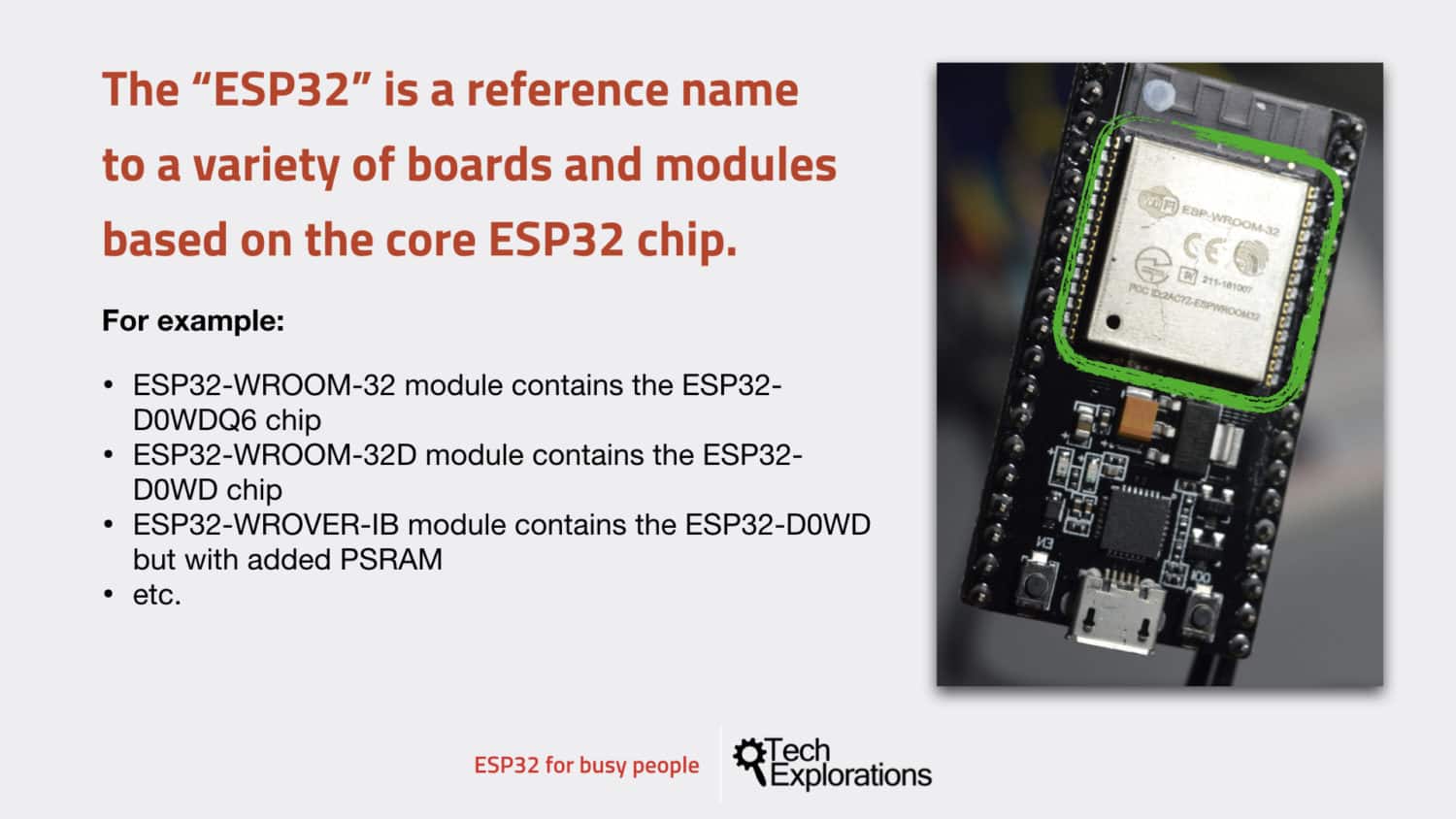
Some of the ESP32 module models
Each of those modules and chip combinations has its own characteristics, and it’s optimized for a particular purpose. Typically, the variation has to do with how much memory is available, whether or not there is pseudo-static RAM, the kind of antenna that they use, or whether they use a single or a dual-core processor, and so on.
The module in the development kit that I’ll be using in this course has got a chip with a “D” in its name, which denotes “dual core.”
My dev kit contains the ESP32 WROOM32 module, which, in turn, contains the ESP32 D0WDQ6 chip. This chip provides four megabytes of flash memory that we can use to store our programs and data. It contains no pseudo-static RAM, and it has a “MIFA” antenna. “MIFA” stands for “meandered inverted F” antenna.
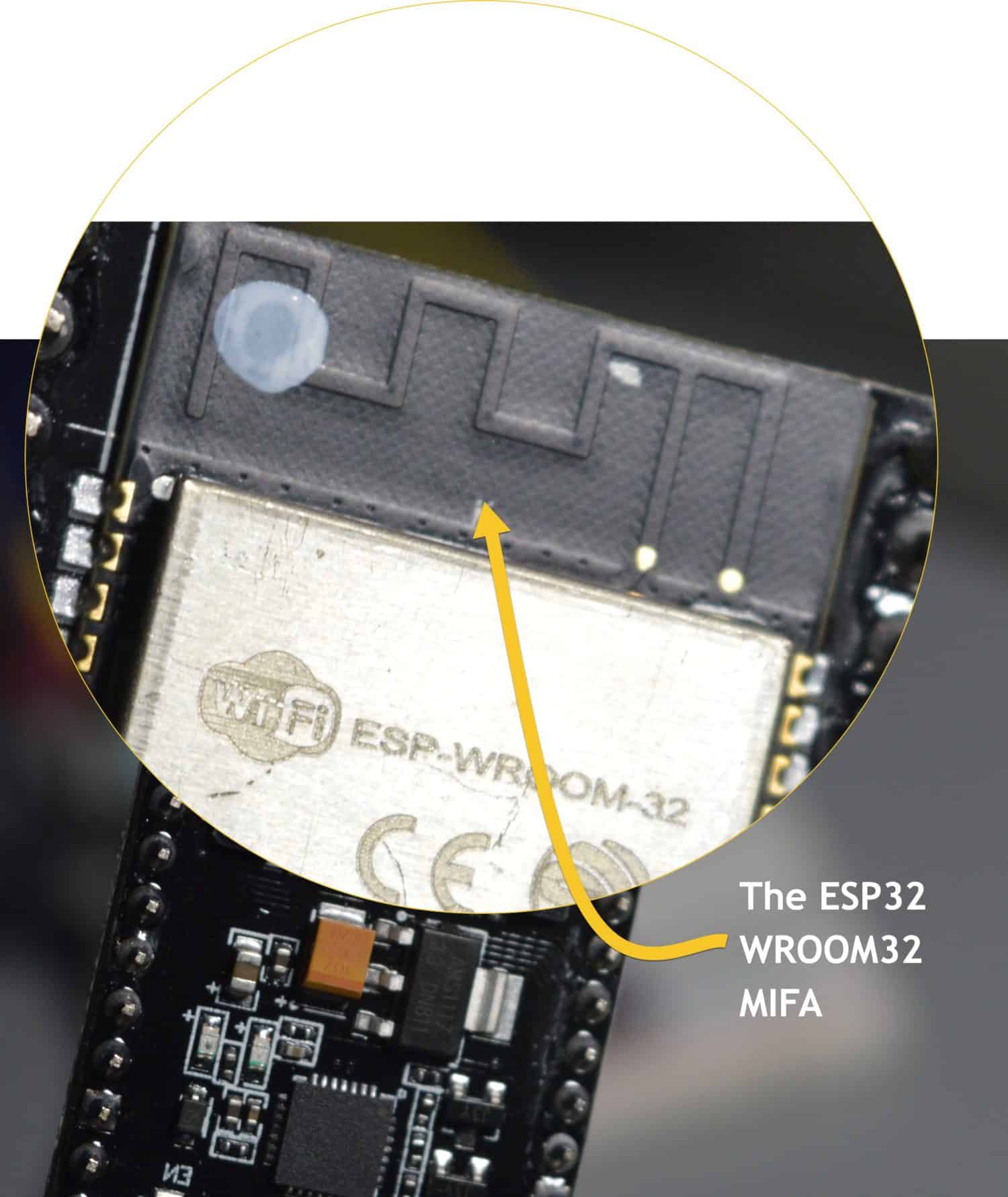
The ESP32 WROOM32 MIFA antenna.
You can see the antenna at the top edge of the board with its zigzag pattern (see photo above). This antenna is a good fit for the ESP32 because of the small amount of available board space allocated to the antenna. We want this antenna to be etched on the PCB itself, instead of having to connect an external component for the antenna. And because there’s not much space on the board, a MIFA antenna uses a meander shape, so that we end up with a full electrical length antenna that fits at this small available space.
The ESP32 WROOM32 D and U
The ESP32 WROOM32-D and ESP32 WROOM32-EU variants also contain the D0WDQ6.
These still have four-megabyte flash memory, and no pseudo-static RAM. The D model still has an integrated MIFA antenna.
But the “U” model has a connector that allows us to connect an external antenna.
In addition, both of those variants are smaller than the “regular” ESP32 WROOM32.
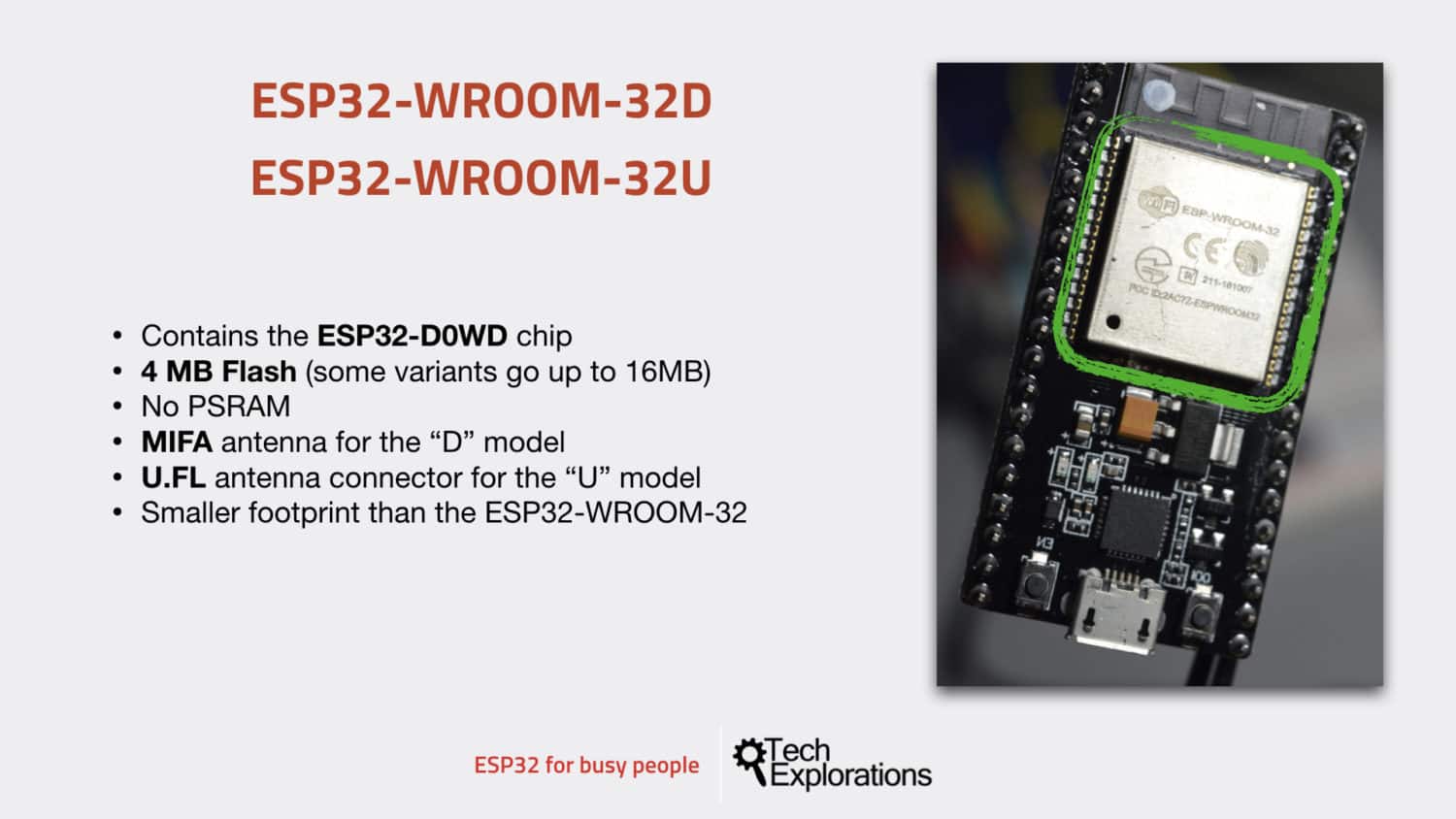
The WROOM-32D and WROOM-32U modules
The ESP32 WROVER
The WROVER variant is also more powerful compared to the WROOM models.
In summary, they have the same amount of flash as the WROOM modules. They contain SPI pseudo-static RAM (WROOM models have none).
They are available with an integrated MFA antenna or an external USFL antenna, and they have variants that can operate with as low as one point eight volts and up to one hundred and forty-four megahertz of clock speed.
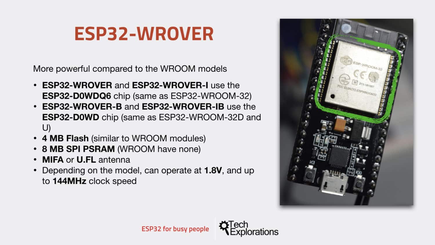
The ESP32 WROVER modules
The ESP32 block diagram
Below, you can see the ESP32 D0WDQ6 module block diagram. It provides a map of all the hardware that is embedded in this microcontroller. In a sense, this diagram provides a summary of the module’s capabilities.
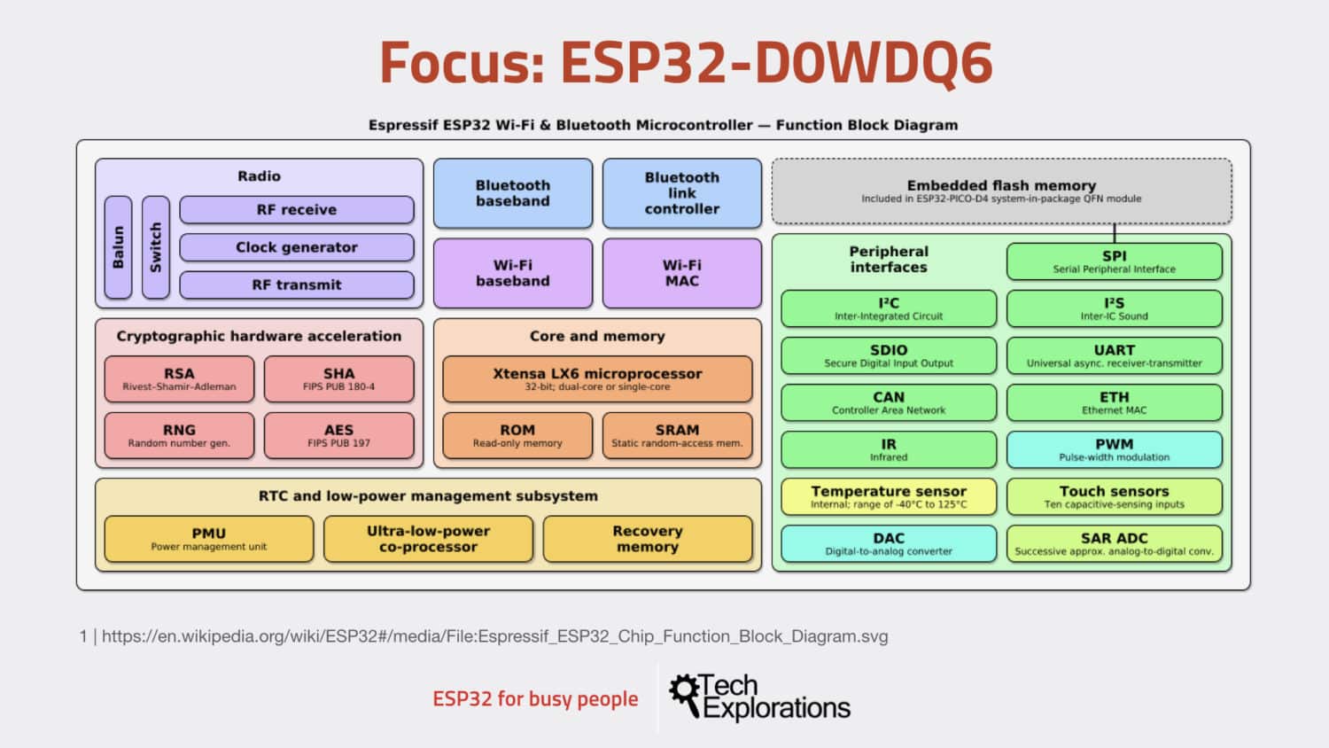
The ESP32 D0WDQ6 module block diagram
At the center, you can see the two XTENSA LX6 microprocessors, with the ROM and static RAM.
At the top left of this diagram, you can see the radio hardware, including the Wi-Fi and Bluetooth. On the right side is the embedded flash memory, where we store our programs and other data and files; the peripheral interfaces, I2C, and SPI, among many others.
There’s also cryptographic hardware acceleration so that we can use TLS and SSL encryption when we are communicating with the Internet.
And, there is also a low power management system subsystem down the bottom left of this diagram.
Conclusion
To wrap this lesson, see below a summary of the hardware features of the ESP32 D0WDQ6.
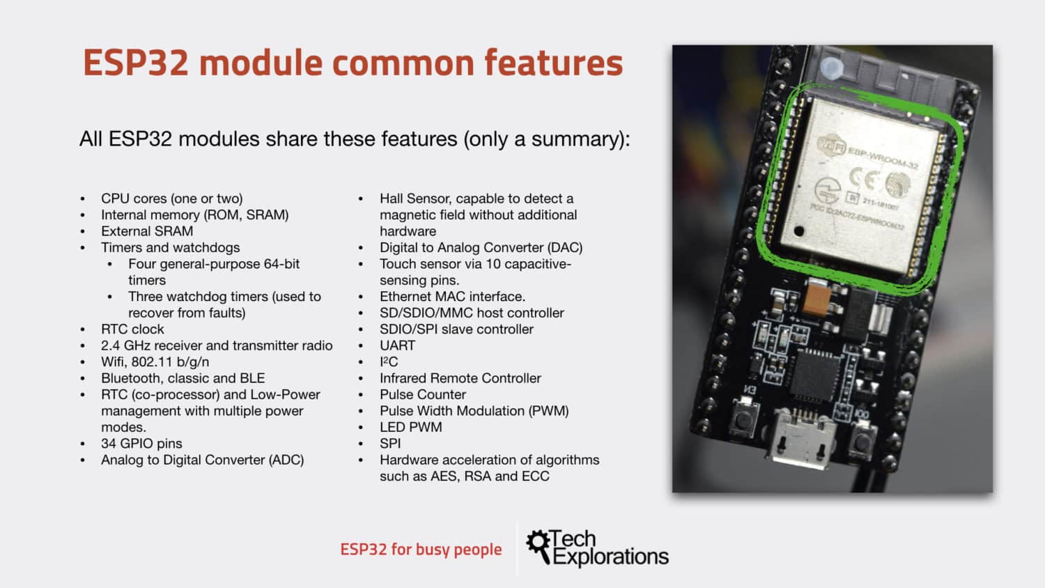
A summary of the hardware features of the ESP32 D0WDQ6
Go on to the next lecture and have a look at the ESP32 development kit.
Ready for some serious learning?
Enrol to
ESP32 for Busy People
This is our comprehensive ESP32 course for Arduino Makers.
It's packed with high-quality video, mini-projects, and everything you need to learn Arduino from the ground up.
Just click on the big red button to learn more.
Jump to another article
Lessons
1: The ESP32 module
2: The ESP32 Devkit
3: The ESP32 vs Arduino
4: The ESP32 GPIOs
5: The ESP32 communications
6: The ESP32 devkit power supply
7: Setting up ESP32 in the Arduino IDE on Mac OS
8: Setting up ESP32 in the Arduino IDE on Windows 10
9: Install the drivers CP2102 for the USB bridge chip
10: Digital output LED
11: Digital output PWM
Last Updated 2 years ago.
We publish fresh content each week. Read how-to's on Arduino, ESP32, KiCad, Node-RED, drones and more. Listen to interviews. Learn about new tech with our comprehensive reviews. Get discount offers for our courses and books. Interact with our community. One email per week, no spam; unsubscribe at any time
