
As a programmer, you are constantly seeking ways to optimize your code and improve its efficiency. One technique that often goes overlooked, particularly by new Arduino programmers, is bitwise operations. It may sound like a scary and complex topic, but in reality, it is a skill that can be easily understood and applied one you read this article.
So, what exactly is bit manipulation? In simple terms, it involves manipulating individual bits within binary numbers. Computers store and process information in binary form, consisting of zeroes and ones, known as bits. Bit manipulation allows us to perform operations at a granular level, making it an incredibly powerful tool for optimizing code and conserving memory.
One of the key advantages of using bit manipulation is its ability to save memory. In many programming applications, memory usage is a critical factor. We can significantly reduce memory consumption by manipulating individual bits instead of using larger data types. This is particularly important in embedded systems like Arduino, where resources are often limited. Efficient memory usage not only improves the performance of your program but also allows you to work within the constraints of the hardware you are using.

Another reason why bit manipulation is important is its speed. Bit operations are typically much faster compared to their equivalent arithmetic or logical operations. This is because microprocessors have dedicated hardware for such operations, which execute them more efficiently. By leveraging bit manipulation techniques, you can achieve significant speed improvements in your code, especially when dealing with large amounts of data or time-sensitive applications.
Bit manipulation also enables you to perform complex operations with simple and concise code. By combining bitwise operators, such as AND, OR, XOR, and shift, you can perform actions like setting specific bits, toggling their values, or extracting subsets of data quickly and efficiently. This level of control over individual bits allows for more nuanced and optimized algorithms, enhancing the overall performance of your program.
Before I go any further, you should know that I have written a much shorter and simpler article about bitwise operators. You can find it here. However, if you are interested in all the glorious details (and have a couple of hours free), continue to read.
To follow the remainder of this tutorial, it is crucial that you understand how the binary system works. If you need help in this area, one good place to start is the Wikipedia article on the binary system.
Now that we understand the importance of bit manipulation let’s address the fear factor surrounding this technique. Many new Arduino programmers tend to avoid bit manipulation because it sounds daunting and unfamiliar. However, with the right introduction and guidance, anyone can master this technique.
To get started, it is recommended to familiarize yourself with the basic bitwise operators and their applications. Online tutorials, forums, and Arduino documentation can serve as valuable resources for learning and understanding these operators. Additionally, experimenting with small code snippets that involve bit manipulation can help solidify your understanding of these concepts.
Once you feel comfortable with the basics, try incorporating bit manipulation techniques into your projects. Start small, and gradually increase the complexity of your programs as your confidence grows. Don’t be afraid to ask for help from more experienced programmers or seek out online communities dedicated to Arduino and bit manipulation. Collaborating and learning from others will accelerate your progress and open doors to new possibilities.
This article is here to help.
By the way, to help you play with the example programs below, I have used the wokwi online Arduino simulator. With wokwi you can try the programs in this article in your browser. No need for the real Arduino board (although that will also work, of course).
Basic Concepts of Bit Manipulation
A bit is the smallest unit of data in computing, representing either a 0 or a 1. Bit manipulation allows programmers to perform various operations at the bit level, such as setting, clearing, toggling, and checking the value of specific bits.
In the Arduino development board context, bit manipulation is especially important due to the limited computational resources and memory available. It allows programmers to optimize code and efficiently work with the board’s registers and input/output (I/O) pins.
Some basic concepts involved in bit manipulation in Arduino include:
1. Bitwise Operators: These operators, such as AND (&), OR (|), XOR (^), and NOT (~), allow programmers to manipulate bits by performing logical operations on individual bits of binary numbers. For example, the bitwise AND operator can be used to check if a specific bit is set (1) or cleared (0) in a binary number.
2. Bit Masks: A bit mask is a binary number used to select or isolate specific bits within a larger binary value. By using bitwise operators with bit masks, programmers can manipulate individual bits while leaving the others intact. For example, a bit mask with a 1 in the desired bit position and 0s elsewhere can be used to set a specific bit.
3. Bitwise Shift Operators: The bitwise shift operators, such as left shift (<<) and right shift (>>), allow programmers to shift bits to the left or right. This operation effectively multiplies or divides a binary number by powers of 2. Bitwise shifting is commonly used to efficiently manipulate individual bits within larger data types, such as integers, on the Arduino board.
4. Register Manipulation: The Arduino board has various registers that control its functionality, such as I/O pins, timers, and serial communication. Bit manipulation is often used to access and modify these registers directly, enabling precise control and efficient use of resources.
Let’s look at the various operators that we use to manipulate bits. These are referred to as “Bitwise operators”.
Bitwise Operators
A bitwise operator is an operator used in computer programming to perform operations on individual bits of binary numbers. It is called a bitwise operator because it operates on the operands’ individual bits, or binary digits. These operators allow for efficient manipulation and control of binary data at the bit level, enabling programmers to perform logical and arithmetic operations at a very low level of a computer’s architecture.
Below, you can find descriptions and example code of the bitwise operators that are regularly used in bit manipulation in Arduino programs.
AND Operator (&)
The “AND Operator” allows you to combine conditions in order to obtain a desired result. It is denoted by the symbol “&” (a single ampersand) and is used to evaluate multiple conditions simultaneously. In this article, we will explore the AND Operator and provide two examples to illustrate its usage.
The AND Operator operates by checking whether multiple conditions are true at the same time. It returns “true” only if all the conditions being evaluated are true. If any of the conditions are false, the result will be “false”. This logical operator is commonly used in conditional statements, loops, and boolean expressions.
Program 1: Turning off specific bits
Play with this program in wokwi.com (the online Arduino simulator).
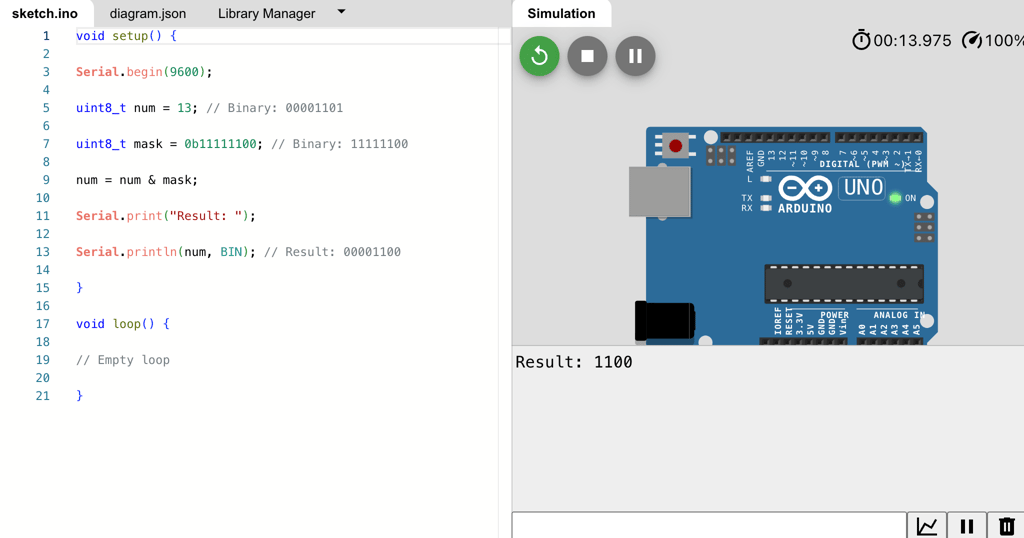
void setup() {
   Serial.begin(9600);
   uint8_t num = 13; // Binary: 00001101
   uint8_t mask = 0b11111100; // Binary: 11111100
   num = num & mask;
   Serial.print("Result: ");
   Serial.println(num, BIN); // Result: 00001100
}

void loop() {
   // Empty loop
}
This program uses the bitwise AND operator (&) to manipulate bits and turn off specific bits in the “num” variable.
- The “num” variable is initially set to 13, which is represented in binary as 00001101.
- The “mask” variable is set to 0b11111100, which is a bit pattern with the desired bits to be turned off set to 0 and the rest set to 1.
- The line `num = num & mask;` performs the bitwise AND operation on “num” and “mask”. This operation compares each corresponding bit in “num” and “mask” and sets the resulting bit to 1 only if both bits are 1. Otherwise, it sets the resulting bit to 0.
- After the bitwise AND operation, the “num” variable becomes 00001100, which is 12 in decimal representation.
- The resulting value, 12, is then printed to the Serial Monitor in binary format.
Program 2: Extracting specific bits
Find this program on Wikwi.
void setup() {
   Serial.begin(9600);
   uint8_t num = 13; // Binary: 00001101
   uint8_t mask = 0b11110000; // Binary: 11110000
   uint8_t extractedBits = num & mask;
   Serial.print("Extracted bits: ");
   Serial.println(extractedBits, BIN); // Extracted bits: 0000xxxx
}

void loop() {
   // Empty loop
}
This program uses the bitwise AND operator (&) to extract specific bits from the “num” variable.
- The “num” variable is initially set to 13, which is represented in binary as 00001101.
- The “mask” variable is set to 0b11110000, which is a bit pattern where the desired bits to be extracted are set to 1 and the rest set to 0.
- The line `uint8_t extractedBits = num & mask;` performs the bitwise AND operation on “num” and “mask”. This operation compares each corresponding bit in “num” and “mask” and sets the resulting bit to 1 only if both bits are 1. Otherwise, it sets the resulting bit to 0.
- After the bitwise AND operation, the “extractedBits” variable contains the specific bits extracted from “num”. In this case, the resulting value is 0000xxxx, representing the four most significant bits of “num”.
- The extracted bits are then printed to the Serial Monitor in binary format.
OR Operator (|)
The bitwise “OR” operator (“|”) is a binary operator that performs an OR operation on each pair of corresponding bits of its operands. It returns a result where each bit position is set to 1 if at least one of the corresponding bits in the operands is a 1.
Some typical use cases where the bitwise OR operator is useful are:
- Setting or adding specific flag values: By using the bitwise OR operator, you can combine multiple flag values into a single variable. Each flag can represent a specific condition or option. For example, in a program that controls settings for a device, you can define different flags for various features (e.g., flag 1 for option A, flag 2 for option B, etc.), and then use the OR operator to set or add these flags together to represent the desired combination of options.
- Bitmasking: Bitmasking is the process of using individual bits in a binary number to represent specific states or options. The bitwise OR operator can be used to combine bitmasks to create complex combinations of states or options. It allows you to set multiple bits to 1, while leaving other bits unchanged, by OR-ing them with a bitmask.
Here are two program examples in Arduino C++ where the bitwise OR operator is used:
Program 1: Setting or adding specific flag values
Find this program on Wikwi.
void setup() {
   Serial.begin(9600);

  int optionA = 1; // Flag 1
  int optionB = 2; // Flag 2
  int optionC = 4; // Flag 3

  // Combining options using the bitwise OR operator
  int combinedOptions = optionA | optionB | optionC;

  // Checking if specific options are present

  if (combinedOptions & optionA) {
    // Option A is present
    Serial.println("Option A");
  }

  if (combinedOptions & optionB) {
    // Option B is present
    Serial.println("Option B");
  }

  if (combinedOptions & optionC) {
    // Option C is present
    Serial.println("Option C");
  }
}

void loop() {
   // Empty loop
}
In this program, we define three flags (optionA, optionB, optionC) representing specific options. By using the bitwise OR operator, we combine these flags into the variable combinedOptions.
Each flag is assigned a unique power of 2 (1, 2, 4) to ensure that each flag occupies a different bit position in the combinedOptions variable.
We then use the bitwise AND operator (&) to check if specific options are present by comparing the combinedOptions variable with individual flags.
Program 2: Bitmasking
Find this program on Wikwi.
void setup() {
  Serial.begin(9600);

  int bitmask = 0b1101; // Bitmask to represent various options

  // Checking specific options using the bitwise OR operator

  if (bitmask & 0b0100) {
    // Option C is present
    Serial.println(("Option C is present"));
  }

  if (bitmask & 0b1000) {
    // Option D is present
    Serial.println(("Option D is present"));
  }
}

void loop() {
   // Empty loop
}
In this program, we define a bitmask (bitmask) to represent various options. The number 0b1101 is a binary literal that sets specific bits in the bitmask.
The bitwise OR operator is used to check if specific options are present by comparing the bitmask with individual bitmasks (0b0100 and 0b1000).
If a specific option is present (represented by a 1 in the corresponding bit position), the condition evaluates to true and the associated actions are performed.
XOR Operator (^)
The bitwise “XOR” operator (“^”) is a binary operator that performs the exclusive OR operation on the individual bits of two binary numbers. It compares corresponding bits of two operands and returns 1 if the bits are different, and 0 if they are the same.
The bitwise XOR operator can be useful in various programming scenarios, including:
- Swapping values: The XOR operator can be used to swap the values of two variables without needing a temporary variable. It works by XORing both variables with each other, canceling out the common bits and leaving behind the XORed bits, effectively swapping the values.
- Encrypting data: XOR can be used as a simple encryption technique by XORing the data with a constant key. It is a reversible operation, as XORing the encrypted data with the same key will retrieve the original data.
Now, let’s see two program examples in Arduino C++ that demonstrate the usage of the bitwise XOR operator:
Example 1: Swapping values using XOR operator
Find this program on Wikwi.
void setup() {
  // put your setup code here, to run once:
  Serial.begin(9600);

  int a = 5; // initial value of variable a
  int b = 8; // initial value of variable b

  a = a ^ b; // XOR operation to swap values

  b = a ^ b; // XOR operation to swap values

  a = a ^ b; // XOR operation to swap values

  // After execution, the values of a and b will be swapped
  Serial.print("a=");
  Serial.println(a);
  Serial.print("b=");
  Serial.print(b);

}

void loop() {
  // put your main code here, to run repeatedly:

}
In this example, the XOR operator is used to swap the values of variables “a” and “b” without using a temporary variable.
The XOR operation cancels out the common bits, resulting in swapping the values.
Example 2: Simple encryption using XOR operator
Find this program on Wikwi.
void setup() {
  // put your setup code here, to run once:
  Serial.begin(9600);

  char message[] = "Hello, World!"; // original message
  char key = 'K'; // encryption key

  int len = strlen(message);

  for (int i = 0; i < len; i++) {
    message[i] = message[i] ^ key; // XOR operation with key to encrypt character
  }

  // After execution, the contents of the message will be encrypted
  Serial.println(message);
}

void loop() {
  // put your main code here, to run repeatedly:
}
In this example, each character of the message string is encrypted by XORing it with the key character. The same key can be used to XOR the encrypted data and obtain the original message.
Overall, the XOR operator in Arduino C++ allows for bitwise manipulation and can be utilized in various scenarios such as swapping values and simple encryption techniques.
NOT Operator (~)
The bitwise “NOT” operator (“~”) is a unary operator that performs a bitwise negation operation on each bit of a binary number. It flips the bits, turning 0s into 1s and 1s into 0s. It is useful for situations that require manipulating individual bits in a binary representation.
One typical use case of the bitwise NOT operator is to toggle individual bits in a binary number. By applying the “NOT” operator to a specific bit, it will flip its value. This can be useful when you need to invert a flag or switch between two states.
Another common use case is in bitwise operations, where the “NOT” operator is used in combination with other operators like AND, OR, or XOR. It allows for complex manipulations of bitwise values, such as masking or clearing specific bits.
Here are two program examples showing the usage of the bitwise NOT operator in Arduino C++:
Example 1: Toggling an LED using the bitwise NOT operator
Find this program on Wikwi.
const int LED_PIN = 13;
unsigned char ledState = 0;

void setup() {
  pinMode(LED_PIN, OUTPUT);
}

void loop() {
  ledState = ~ledState; // Toggle the value of ledState using the NOT operator
  digitalWrite(LED_PIN, ledState);
  delay(1000);
}
In this example, the program toggles an LED connected to pin 13 on the Arduino board.
The variable ledState is used to store the current state of the LED, which can be either 0 or 1.
By applying the bitwise NOT operator to ledState (~ledState), the value is inverted, effectively toggling between 0 and 1.
The result is then used to control the state of the LED using digitalWrite().
Example 2: Clearing specific bits using the bitwise NOT operator
Find this program on Wikwi.
const byte DATA_MASK = B11001100;
byte data = B10101010;

void setup() {
  Serial.begin(9600);

  byte clearedData = data & ~DATA_MASK; // Clear specific bits using the NOT operator

  Serial.println(clearedData, BIN);

}

void loop() {
  // The loop function is not used in this example
}
In this example, the program demonstrates how to clear specific bits in a binary number using the bitwise NOT operator. The constant DATA_MASK represents the bits that need to be cleared, and data is the binary number to modify.
By performing the operation data & ~DATA_MASK, the bits specified in DATA_MASK are cleared, while the rest of the bits remain unchanged. The resulting value clearedData is then printed to the serial monitor for verification.
These examples illustrate how the bitwise NOT operator can be used to toggle or manipulate specific bits in binary numbers, allowing for more granular control and manipulation of data in Arduino C++.
Left Shift Operator (<<)
The bitwise “Left shift” operator (“<<“) is a binary operator that shifts the bits of a number to the left by a specified number of positions. Each shift multiplies the original number by 2.
One typical use case of the bitwise left shift operator (“Left Operand”) is to perform quick multiplication or division by powers of 2. Shifting the bits to the left is equivalent to multiplying the number by 2 raised to the power of the shift amount. This operation is efficient and faster than actual multiplication or division operations, especially for microcontrollers with limited processing power.
Here are two program examples written in Arduino C++ that demonstrate the use of the bitwise left shift operator:
Example 1: Shift bits to left
Find this program on Wikwi.
void setup() {
  Serial.begin(9600);

  int originalNumber = 5;
  int shiftAmount = 2;

  int result = originalNumber << shiftAmount;

  // The binary representation of 5 is 0000 0101
  Serial.println(originalNumber, BIN);
  // Shifting left by 2 positions gives us 0001 0100, which is 20 in decimal
  Serial.println(result, BIN);

}

void loop() {
  // The loop function is not used in this example
}
In this example, we have an original number of 5 (in binary: 101), and we shift its bits to the left by 2 positions using the left shift operator.
The result will be 20 (in binary: 10100), which is obtained by multiplying the original number by 2 raised to the power of the shift amount.
Example 2: Check specific bit value
Find this program on Wikwi.
void setup() {
  Serial.begin(9600);

  unsigned int value = 10;
  unsigned int mask = 1 << 3;

  bool isFirstBitSet = (value & mask) != 0;

  // The binary representation of 10 is 0000 1010
  Serial.println(value,BIN);

  // Shifting the bit 1 to the left by 3 positions gives us 0000 1000
  Serial.println(mask,BIN);

  // The bitwise AND operation with 0000 1000 checks if the bit is set or not
  Serial.println(isFirstBitSet,BIN);

}

void loop() {
  // The loop function is not used in this example
}
In this example, we have a value of 10, and we want to check if the third bit (from the right) is set or not. We achieve this by creating a mask, which has the third bit set and the rest cleared, using the left shift operator.
Then, we perform a bitwise AND operation between the value and the mask. If the result is non-zero, it means the third bit is set.
In both examples, the left shift operator allows us to perform efficient operations on binary numbers, enabling quick multiplication and division by powers of 2, as well as checking specific bits’ values.
Right Shift Operator (>>)
The bitwise “Right shift” operator (“>>”) is used to shift the bits of a number to the right by a specified number of positions. This operator works by taking the binary representation of a number and moving each digit to the right by the specified number of positions, discarding the bits that fall off.
Typical use cases where the bitwise right shift operator is useful include:
- Division by powers of 2: When dividing a number by a power of 2 (2^n), using the right shift operator is more efficient than using conventional division. Shifting the bits to the right by n positions is equivalent to dividing the number by 2^n.
- Fast multiplication or division by 2: Shifting the bits to the right by one position (equivalent to dividing by 2) or left by one position (equivalent to multiplying by 2) is a common optimization technique used in programming when performance is a concern. It is faster and more efficient than using conventional multiplication or division.
Here are two example programs written in Arduino C++ that demonstrate the use of the bitwise right shift operator:
Example 1: Division by a power of 2
Find this program on Wikwi.
void setup() {
  Serial.begin(9600);

  int number = 16;
  int powerOfTwo = 4; // 2^4 = 16

  int result = number >> powerOfTwo;

  // After shifting the bits of the number to the right 4 positions,
  // the result will be 1 (16 divided by 2^4)

  Serial.print("Result: ");
  Serial.println(result);
}

void loop() {
  // The loop function is not used in this example
}
In this example, the number 16 is divided by 2^4 (which is 16).
By shifting the bits of the number to the right by 4 positions, we get the result of 1.
Example 2: Fast multiplication by 2
Find this program on Wikwi.
void setup() {
  Serial.begin(9600);

  int number = 5;

  int result = number << 1;

  // After shifting the bits of the number to the left 1 position,
  // the result will be 10, which is equivalent to multiplying 5 by 2

  Serial.print("Result: ");
  Serial.println(result);
}

void loop() {
  // The loop function is not used in this example
}
In this example, the number 5 is multiplied by 2 using the bitwise left shift operator. By shifting the bits of the number to the left by 1 position, we get the result of 10.
In both examples, the bitwise shift operator provides a more efficient way of performing division by a power of 2 and multiplication by 2 respectively, compared to using typical division or multiplication operations.
Reading and setting Bits with special functions
To read input bits in Arduino, you can use the bitRead(), bit(), and bitSet() functions.
The bitRead() function reads a specific bit from a byte value. It takes two arguments: the byte value and the position of the bit to be read. For example, to read the third bit of a byte variable named “input”, you can use bitRead(input, 2) where 2 is the position of the bit.
The bit() function can be used to create a value with a specific bit set. It also takes two arguments: the position of the bit and whether it should be set to 0 or 1. For example, bit(3) will create a value with only the fourth bit set (counting from 0).
The bitSet() function specifically sets a bit within a byte to 1. It takes two arguments: the byte value and the position of the bit to be set. For example, bitSet(input, 1) will set the second bit of the byte variable “input” to 1.
When reading input bits, it’s important to understand the position of the bit being manipulated and whether it is the least significant bit (LSB) or not. This is crucial for accurately computing their values and setting them to 1 using the appropriate function.
Example: bitRead()
Here is an example code that demonstrates the use of the bitRead() function in Arduino C++:
Find this program on Wikwi.
int value = 0b11001010; // Binary representation of a value
int bitPosition = 3; // Position of the bit to read

void setup() {
  Serial.begin(9600);

  int bitValue = bitRead(value, bitPosition);

  Serial.println(bitValue);
}

void loop() {
  // The loop() function is not used in this example
}
In this example, we have a binary value 11001010 stored in the variable value. We want to read the value of the bit at position 3, so we specify bitPosition as 3.
Inside the setup() function, we use the bitRead() function to read the value of the bit at the specified position. The bitRead() function takes two arguments: the value from which we want to read the bit (in this case, value), and the position of the bit we want to read (in this case, bitPosition).
The result is stored in the variable bitValue. In this example, the bit at position 3 of the binary value 11001010 is 0, so the bitValue will be 0.
Finally, we print the bitValue using the Serial.println() function, which will display the result on the Arduino Serial Monitor.
Here is another example for the bitRead() function (find this program on Wikwi):
void setup() {
  Serial.begin(9600); // Initialize serial communication at 9600 baud
}

void loop() {
  int num = 9; // Number to convert to binary

  Serial.print("Binary representation of ");
  Serial.print(num);
  Serial.print(": ");

  for (int i = 7; i >= 0; i--) {
    Serial.print(bitRead(num, i)); // Use bitRead() function to get the value of the i-th bit in the number
  }

  Serial.println(); // Print a new line
  delay(1000); // Delay for 1 second
}
The program above demonstrates the use of the bitRead() function in Arduino C++. The bitRead() function is used to extract the value of a specific bit in a number. In this example, we initialize a variable num with the value 9.
Inside the loop() function, we use a for loop to iterate over each bit of the number num. The loop starts with i being equal to 7 (the most significant bit) and decreases down to 0 (the least significant bit).
Within each iteration, we call bitRead(num, i) to extract the value of the i-th bit from the num variable. The value extracted is then printed using Serial.print().
After printing the binary representation of num, the program waits for 1 second using the delay() function before looping again.
When you upload and run this program on an Arduino board, it will continuously print the binary representation of the number 9 (1001 in binary) over the serial monitor at a baud rate of 9600. The output will appear as follows:
Binary representation of 9: 00001001
Binary representation of 9: 00001001
Binary representation of 9: 00001001
Binary representation of 9: 00001001
This program showcases how the bitRead() function can be used to access and manipulate individual bits of a number, which can be useful in various applications such as bitwise operations, data encoding, and decoding.
Example: bitSet()
Find this program on Wikwi.
void setup() {
  Serial.begin(9600); // Initialize serial communication

  bitSet(DDRB, 2); // Set digital pin 10 (PB2) as an output pin
}

void loop() {
  bitSet(PORTB, 2); // Set digital pin 10 (PB2) HIGH

  delay(1000); // Wait for 1 second

  bitClear(PORTB, 2); // Set digital pin 10 (PB2) LOW

  delay(1000); // Wait for 1 second

}
In this example, we use the bitSet() function in Arduino C++ to set a specific bit in a register. Specifically, we use it to set a specific pin of Port B as an output pin and then toggle the state of that pin in the loop() function.
The bitSet() function takes two arguments: the first argument is the register that we want to modify, and the second argument is the position of the bit that we want to set.
In our example, we set the bit of digital pin 10 (PB2) as an output pin by calling bitSet(DDRB, 2). Here, DDRB represents the register for the Data Direction Register of Port B, and 2 represents the position of the specific bit we want to set.
Inside the loop() function, we use bitSet(PORTB, 2) to set the pin HIGH, and then bitClear(PORTB, 2) to set the pin LOW. This creates a simple blinking LED effect, as the pin is toggled ON and OFF with a delay of 1 second between each state change.
Overall, the bitSet() function allows us to manipulate individual bits in registers, enabling precise control over specific pins and their functionality in Arduino programming.
Arduino Port DDRx Register
The Arduino Port DDRx (Data Direction Register) is a register used to control the direction of data flow for a specific port on an Arduino microcontroller. It allows you to configure each pin of the port as either an input or an output.
The DDRx register is important because it determines whether a pin is capable of sending or receiving data. By setting a specific bit in the DDRx register, you can configure the corresponding pin as an output (logically HIGH or LOW) or an input to read data.
Example uses of the DDRx register include:
- Controlling LEDs: By setting the respective pins of a port as outputs using the DDRx register, you can control LEDs connected to those pins. This allows you to turn the LEDs on or off by simply writing logical HIGH or LOW values to the pins.
- Interfacing with sensors: If you have sensors that provide digital output, such as a PIR motion sensor, you can set the corresponding pins of the port as inputs using the DDRx register. This enables you to read the state of the sensors and trigger actions based on the received data.
Here’s an example code snippet demonstrating the usage of the Arduino Port DDRx register to control LEDs:
Find this program on Wikwi.
const int ledPin = 2; // Example LED pin

void setup() {
  DDRD |= (1 << DDD2); // Set pin 2 of PORTD (Arduino digital pin 2) as OUTPUT
}

void loop() {
  digitalWrite(ledPin, HIGH); // Turn the LED on
  delay(1000); // Wait for 1 second
  digitalWrite(ledPin, LOW); // Turn the LED off
  delay(1000); // Wait for 1 second
}
In the above code, DDRD represents the DDR register for Port D on the Arduino. The statement DDRD |= (1 << DDD2); sets bit 2 in the DDRD register to 1, configuring pin 2 (Arduino digital pin 2) of Port D as an output. The digitalWrite() function is then used to toggle the state of the LED connected to pin 2.
By setting the appropriate bit in the DDRx register, you can control the direction of data flow for individual pins on an Arduino microcontroller, enabling you to interface with various components and devices.
Arduino Port PINx Register
The purpose of the Arduino Port PINx register is to read the status of the pins in a particular port. Each port on the Arduino board consists of multiple pins, and the PINx register allows you to check the status of these pins at any given time.
Some common use cases for the PINx register include:
- Reading digital inputs: You can use the PINx register to read the state of digital input pins. For example, you can use this register to check if a push button connected to a specific pin is being pressed or released.
- Monitoring sensor values: If you have sensors that provide digital outputs, you can use the PINx register to read the values from those sensors. This can be useful for various applications such as measuring temperature, detecting motion, or monitoring environmental conditions.
- Implementing interrupt-based routines: The PINx register can be utilized to trigger interrupt routines when a pin’s state changes. This can be helpful in applications where you want to respond quickly to specific events, such as detecting a falling edge or a rising edge on a pin.
Here’s an example program that demonstrates the usage of the PINx register:
Find this program on Wikwi.
#define BUTTON_PIN 2
#define LED_PIN 13

void setup() {
  DDRD &= ~(1 << DDD2); // set digital pin 2 as input
  DDRB |= (1 << DDB5); // set digital pin 13 as output
}

void loop() {
  if (PIND & (1 << PIND2)) {
    // if button is pressed, turn on LED
    PORTB |= (1 << PORTB5);
  } else {
    // if button is not pressed, turn off LED
    PORTB &= ~(1 << PORTB5);
  }
}
This program uses direct port manipulation to read and write to the pins, which is faster and more efficient than using the digitalRead() and digitalWrite() functions.
However, it’s also more complex and less portable, so it’s generally only recommended for advanced users or specific applications where performance is critical.
The DDRx registers are used to set the data direction of the pins (input or output), the PORTx registers are used to write to the pins, and the PINx registers are used to read from the pins.
The x in these register names should be replaced with the port letter that corresponds to the pin you’re using.
For example, digital pin 2 on the Arduino Uno is on port D, so you would use DDRD, PORTD, and PIND to manipulate this pin. Similarly, digital pin 13 is on port B, so you would use DDRB, PORTB, and PINB to manipulate this pin.
For more information on Port Registers, see the Arduino Language Reference – Port Registers.
How are the PINx and DDRx registers different?
The PINx and DDRx registers are different in terms of their function.
- PINx registers are used to read the status of the individual pins of a microcontroller or microprocessor. They allow you to check whether a specific pin is currently set to a high or low state, which is useful for detecting input signals or checking the state of external devices.
- On the other hand, DDRx registers are used to control the direction of the pins. They determine whether a pin is set as an input or an output. By setting the DDRx register, you can configure a pin to send signals out to other devices as an output or receive signals from other devices as an input.
In summary, PINx registers are used for reading the status of pins, while DDRx registers are used for controlling the direction of the pins.
Frequently asked questions about bit manipulation
To wrap this article up, here is a list of “frequently asked questions” about bit manipulation with the Arduino, and consise answers:
1. What is bit manipulation and why is it important in Arduino programming?
Bit manipulation refers to the manipulation or handling of individual bits within a byte or other data types in a programming language. In Arduino programming, bit manipulation is important because it allows for efficient memory usage and resource optimization. By directly manipulating individual bits, programmers can perform operations such as setting or clearing specific flags or controlling specific hardware pins. This level of control and efficiency is crucial in Arduino programming to ensure optimal performance and utilization of limited resources.
2. How do I set a specific bit in a register using bitwise operations in Arduino?
To set a specific bit in a register using bitwise operations in Arduino, you can use the bitwise OR operator (|) with the desired bit position shifted by the number of bits in the register. For example, to set bit 3 in a register named “reg”, you can use the following code:
reg |= (1 << 3);
3. How can I clear a bit in a register using bitwise operations in Arduino?
To clear a bit in a register using bitwise operations in Arduino, you can use the bitwise AND operator with the complement of the bit you want to clear. For example, to clear bit 3 in a register called “reg”, you can use the following code:
reg &= ~(1 << 3);
This code performs a bitwise AND operation between the current value of “reg” and the complement of a bitmask where only bit 3 is set to 1. The resulting value will have bit 3 cleared.
4. What are some common applications of bit manipulation in Arduino programming?
Some common applications of bit manipulation in Arduino programming include setting or clearing specific bits in a register to control hardware peripherals, bitwise operations for data compression or encryption, and reading or writing individual bits in data packets or communication protocols.
5. How do I toggle a specific bit in an Arduino register?
To toggle a specific bit in an Arduino register, you can use the bitwise XOR operator (^) with a mask that has the desired bit set. This can be done with the following code:
register ^= (1 << bit_number);
Replace “register” with the name of the register you want to modify, and “bit_number” with the number of the bit you want to toggle (0-7 for an 8-bit register). This code will toggle the specified bit, flipping its value from 0 to 1 or from 1 to 0.
6. Can you provide an example of using bit manipulation to control specific hardware in Arduino?
Yes, bit manipulation can be used in Arduino to control specific hardware, such as turning on or off individual LED lights. By manipulating specific bits within a register, we can control the state of an output pin connected to an LED. For example, setting a particular bit in the register to 1 will turn on the LED, while setting it to 0 will turn it off. This allows precise control over hardware components using minimal code and system resources.
7. Are there any predefined functions in Arduino for bit manipulation?
Yes, Arduino provides predefined bitwise manipulation functions such as bitRead(), bitWrite(), bitSet(), bitClear(), and bit() to efficiently manipulate individual bits in variables.
8. What are the potential pitfalls to avoid when using bit manipulation in Arduino programming?
When using bit manipulation in Arduino programming, potential pitfalls to avoid include:
- Misinterpreting or mishandling the bit order, leading to incorrect results.
- Not considering the potential side effects of manipulating bits, such as unintended changes to other variables or registers.
- Neglecting to document and comment the code adequately, making it difficult for others to understand and maintain.
- Relying too heavily on bit manipulation, which can make the code more complex and harder to debug.
- Failing to test and validate the code thoroughly, leading to unexpected behavior or errors.
9. How does bitwise shifting work in Arduino and how can I use it effectively?
Bitwise shifting in Arduino is a programming technique that allows you to shift the bits of a binary number to the left or right. It is done using the bitwise shift operators << for left shift and >> for right shift. Left shifting moves the bits to the left, effectively multiplying the number by 2, while right shifting moves the bits to the right, effectively dividing the number by 2.
You can use bitwise shifting effectively in Arduino to perform operations such as bitwise manipulation, setting or clearing specific bits within a variable, and efficient multiplication or division by powers of 2. It is commonly used for tasks like bit manipulation, working with binary data, and optimizing memory usage in low-level programming applications.
10. What is the performance impact of using bit manipulation in Arduino code compared to other methods?
Bit manipulation in Arduino code can have a significant performance impact compared to other methods. By manipulating individual bits, developers can achieve faster and more efficient operations on binary data. This can result in improved execution speed and reduced memory usage, making it a valuable technique in optimizing Arduino code for performance-critical applications.