
This article was written by Stephane Calderoni and posted on the Tech Explorations discussion space for the course “Oscilloscopes for Busy People”. Steph agreed to “liberate” this article and open it to the world on our Blog; it is an excellent example of how the ATMega328 MCU can perform at a higher level with some clever programming.
Thank you Steph! — Peter
I want to share my experience related to Experiment 2, conducted in Chapter 5 of the Oscilloscope course, to show how to drastically optimize the µController response by taking advantage of the internal registers and interrupt vectors of the ATMega328.
I think it may be of interest to the community. 🙂
I have slightly modified the initial experiment so that :
- The LED changes state each time the button is pressed,
- And I added a simple debouncing algorithm.
Here is my circuit:
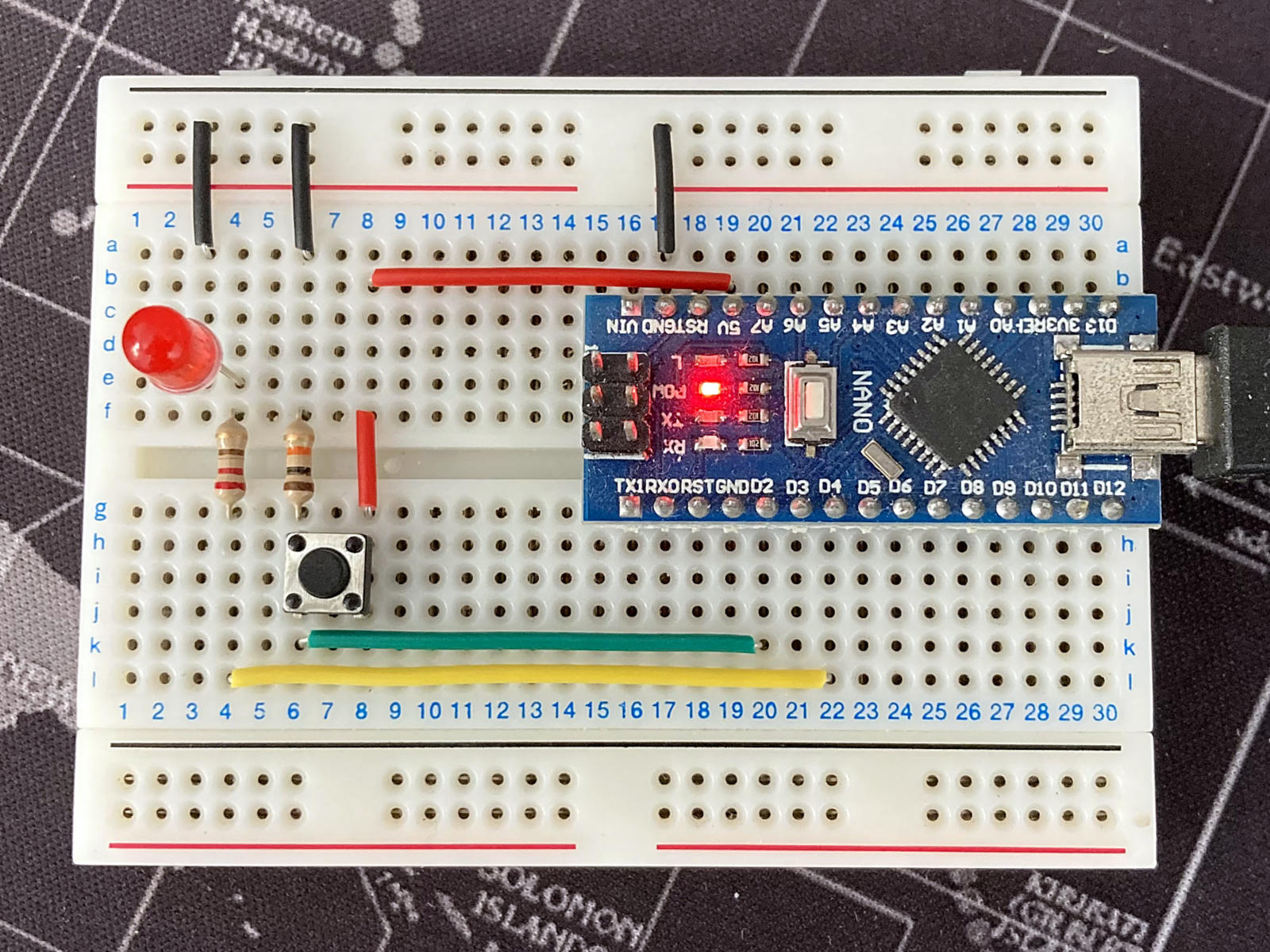
The probes are placed directly on the pins of the Arduino Nano board:
- Pin D4: LED => CH1 (the yellow probe)
- Pin D2: BTN => CH3 (the blue probe)
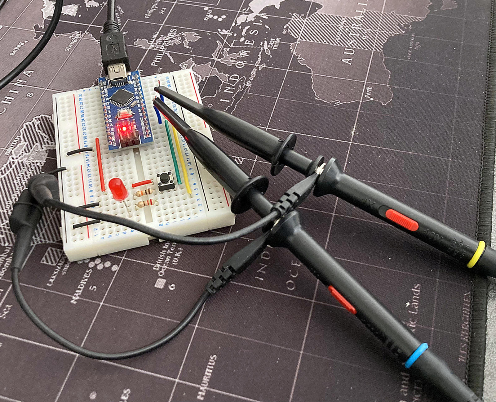
Here is a demo of how the circuit works:
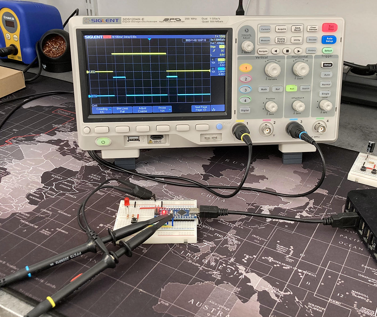
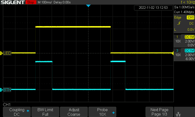
And what we see on the oscilloscope:
Zoom in on the screen:
If we are interested in the reaction time of the Arduino board from the moment we press the button to turn on the LED, we must pay attention to how we implement it.
Indeed, with a classical approach, we can code it like this:
/**
 * ---------------------------------------------------------------------------
 * Control of an LED by a push button with an Arduino Nano board
 * ---------------------------------------------------------------------------
 * Classical approach with the Arduino API
 * ---------------------------------------------------------------------------
 * PIN |
 * ----+----------------------------------------------------------------------
 * D2  | Push button wired up to a pull-down resistor (10 kΩ)
 * ----+----------------------------------------------------------------------
 * D4  | Red LED with a 220 Ω resistor in series
 * ----+----------------------------------------------------------------------
 */

#include <Arduino.h>

#define BTN_PIN 2
#define LED_PIN 4
#define DEBOUNCE_DELAY_MS 1

bool     led_level = LOW;
uint8_t  input;
uint8_t  last_input;
uint8_t  output;
uint32_t last_debounce;

void setup() {
    pinMode(BTN_PIN, INPUT);
    pinMode(LED_PIN, OUTPUT);
}

void loop() {

    uint32_t now = millis();

    input = digitalRead(BTN_PIN);

    if (input != last_input) last_debounce = now;
    last_input = input;

    if (now - last_debounce > DEBOUNCE_DELAY_MS) {
        if (output != input) {
            output = input;
            if (output) {
                digitalWrite(LED_PIN, led_level = !led_level);
            }
        }
    }
}
Let's examine the reaction time of the µController when the button is pressed to turn on the LED:
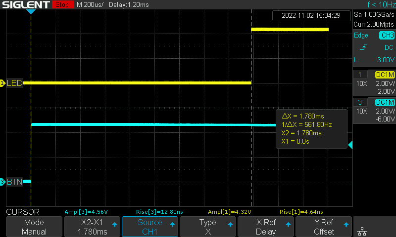
The reaction time here is 1.78 ms.
Several captures of this event give roughly the same order of magnitude.
Now, rather than using the Arduino API’s digitalRead() and digitalWrite() functions, let’s implement things differently, using the ATMega328’s registers and one of its interrupt vectors instead:
/**
 * ----------------------
 * Pinout
 * ----------------------
 * PIN | PORT |
 * ----+------+----------
 * D2  | PD2  | BTN
 * ----+------+----------
 * D4  | PD4  | LED
 * ----------------------
 */

#include <Arduino.h>

#define DEBOUNCE_DELAY_MS 1

ISR(INT0_vect) {
    EIMSK &= ~(1 << INT0);
    PORTD ^= 1 << PD4;
}

void setup() {
    DDRD  &= ~(1 << PD2);
    DDRD  |= 1 << PD4;
    EICRA  = (1 << ISC01) | (1 << ISC00);
    EIMSK  = 1 << INT0;
    SREG  |= 1 << SREG_I;

}

void loop() {

    static uint32_t last = 0;
           uint32_t now  = millis();

    if (!(EIMSK >> INT0) && now - last > DEBOUNCE_DELAY_MS) {

        last = now;

        if (!((PIND >> PD2) & 0x1)) {
            EIFR  = 1 << INTF0;
            EIMSK = 1 << INT0;
        }
    }
}
You can find a documented version of my code on GitHub Gist, if you are interested. 😉
And now, let us observe the reaction time of the µController:
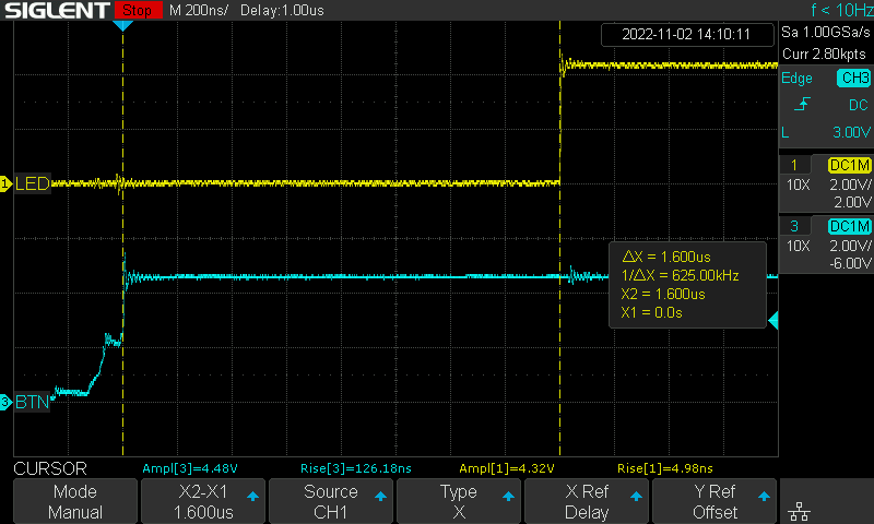
The reaction time here is 1.6 µs. 💪 😎
Several captures of this event give roughly the same order of magnitude.
In other words, the µController reacts 1000 times faster!
How great is that? 🍾 🥂
This is the advantage of using the specificities of the ATMega328 by relying on low-level programming; certainly more challenging to read when you are not used to it, but so much more efficient than the Arduino API.
To go to the end of the experiment, let’s observe the bouncing window when we press the button:
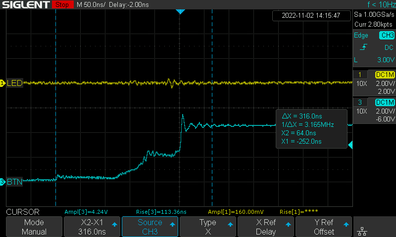
The signal stabilizes after 316 ns, which is not bad at all. The button I use here is quite good: the signal permanently stabilizes before the 800 ns limit. That’s why I set the DEBOUNCE_DELAY_MS value to 1 ms in my code.
So, I hope this little experiment has drawn your attention to the importance of implementation choices. For some applications, it is sometimes necessary to obtain the fastest possible response time. 😉
If you want to do some more reading and drill into some of the concepts I mentioned in this article, please refer to these resources:
- The ATMega328P official documentation, where you can find details on the registers etc.
- This guide by Nick Gammon, for information on how to handle interrupts.
- Here is the code from this project on Github.