
Capacitors are fundamental components in electronic circuits, and understanding how they work is crucial for anyone looking to build and design their own circuits. In this segment, we’ll explore the various kinds of capacitors you can use in your circuits, the capacitor symbols, and how to calculate values in simple circuits that contain capacitors and resistors.
This is content from an update to Basic Electronics for Arduino Makers (or maybe a new course?! - I haven't decided yet) that I'm working on.

I want to take some time and return to the basics, and that is analog electronics. I am looking at the fundamental laws of electronics, their mathematics, discreet analog components, and how to use simulation and practical experiments with a breadboard and bench instruments (like a power supply, multimeter, oscilloscope and signal generator) to promote learning.

This is the first draft of the section on capacitors that I plan to publish as a video course and a book.

I would love to know what you think about a course on analog electronics. Is it worth the effort? If yes, what would you like to learn in such course?
Capacitors and Their Role in Electronics
Capacitors are essential components in electronics, playing a vital role in various circuits. A capacitor is a passive electrical component that stores and releases electrical energy. It consists of two conductive plates separated by an insulating material called a dielectric.
What do capacitors do?
In electronics, capacitors store and release electrical energy, functioning as temporary energy storage devices. This property is useful in applications like power supplies, where capacitors help maintain a steady voltage by providing energy during short interruptions.
Capacitors are used to smooth voltage fluctuations, filter noise, and control circuit timing. This feature is particularly useful in devices like power supplies. Capacitors can filter noise and provide a cleaner DC voltage by blocking AC components while allowing DC components to pass through.
Capacitors can couple AC signals between different circuit stages while blocking DC components. This is known as AC coupling. Coupling involves connecting two circuits so that a signal can pass from one to the other while maintaining certain desired properties and blocking undesired components. It is particularly important in multi-stage amplifiers, audio equipment, and signal-processing circuits.
Conversely, decoupling capacitors isolate different parts of a circuit, preventing unwanted interference by bypassing AC noise to the ground. Decoupling refers to using capacitors to isolate different circuit parts, preventing unwanted interactions and ensuring stable operation. This process helps maintain a clean and stable power supply by filtering out noise and fluctuations. Decoupling or bypass capacitors are placed across power supply lines and between power and ground in electronic circuits. Their primary function is to smooth out voltage fluctuations and provide a local charge reservoir.
Capacitors also fulfill a variety of other roles, such as:
- Creating time delays and generating oscillating signals. Capacitors are crucial in timing applications. Combined with resistors, they form RC circuits that can create time delays or generate oscillating signals. These circuits are used in clocks, timers, and oscillators.
- Tuning a circuit’s frequency response. In radio frequency (RF) circuits, capacitors are used for tuning and resonance. Adjusting the capacitance can alter a circuit’s frequency response, allowing it to filter or amplify specific frequencies selectively.
- Capacitors facilitate efficient energy transfer. In switching power supplies and DC-DC converters, capacitors facilitate efficient energy transfer between different voltage levels. By storing and releasing energy rapidly, they help maintain the desired output voltage.
Most of these capacitor applications are useful in more advanced circuits, and you will learn about them later in your electronics training. RC circuits, where capacitors work in conjunction with resistors, are widely used in filters, oscillators, and timing circuits. The combination of resistors and capacitors in these circuits determines the circuit’s time constants and overall behavior. You will learn about RC circuits in this course segment because they are common.
Types of capacitors
Different capacitors, such as electrolytic, ceramic, and tantalum, have specific characteristics suited for different applications. Here, I summarize the features and use cases of electrolytic, ceramic, and tantalum capacitors.
Here is a table summarizing the features and use cases of electrolytic, ceramic, and tantalum capacitors:
| Feature/Use Case | Electrolytic Capacitors | Ceramic Capacitors | Tantalum Capacitors |
|---|---|---|---|
| Capacitance Range | High (µF to mF) | Wide (pF to µF) | High (µF) |
| Polarization | Polarized | Non-Polarized | Polarized |
| Voltage Rating | Moderate to high | High | High |
| Physical Size | Larger for given capacitance | Small | Compact |
| Temperature Stability | Moderate | High (C0G/NP0), Moderate (X7R) | High |
| High Frequency Performance | Moderate | Excellent | Moderate |
| Reliability | Moderate | High | High |
| Common Use Cases | Power supply filtering, coupling, decoupling, timing circuits | Decoupling, high-frequency circuits, general-purpose | Decoupling, filtering, portable electronics, audio circuits |
| Special Features | High capacitance values, low cost | Wide range of capacitance, excellent high-frequency performance | High capacitance in compact size, long-term reliability |
This table compares the key features and common use cases for each type of capacitor, making it easier to understand their applications in electronic circuits.
Capacitor Symbols
Capacitors are represented by various symbols in circuit diagrams. I have created a table (see below) to show these symbols. There are capacitor symbols for regular (un-polarised) capacitors, polarised, electrolytic, variables, and more. Symbols vary across geographical regions, most commonly under the ANSI (American National Standards Institute, primarily used in the United States) or IEC (International Electrotechnical Commission, widely used in Europe) standards.
Here is a table showing the symbols used to denote different types of capacitors in electrical circuit diagrams:
| Capacitor Type | Symbol Description | Symbol |
|---|---|---|
| General Capacitor | Two parallel lines | 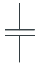 |
| Polarized Capacitor | One straight line and one curved line | 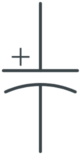 |
| Electrolytic Capacitor | One straight line (positive) and one curved line (negative) | |
| Variable Capacitor | Two parallel lines with an arrow through one line | 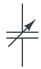 |
This table helps visualize the symbols used for different types of capacitors in circuit diagrams, making it easier to identify them when working with schematics.
Capacitors in Series and Parallel Configurations
When capacitors are connected in series, their total capacitance decreases inversely proportional to the sum of reciprocals of individual capacitances. This configuration is useful for applications where a specific capacitance value is needed. On the other hand, when capacitors are connected in parallel, their total capacitance increases, which is beneficial when higher capacitance values are required.
Here are the mathematical formulas that describe capacitors in parallel and series configurations:
- In parallel: Ctotal = C1 + C2 + C3
- In series: 1/Ctotal=1/C1+1/C2+1/C3
Here are two examples of using these formulas in circuits with three capacitors.
Example 1: Capacitors in Parallel
Imagine we have three capacitors connected in parallel, with the following capacitances:
- Capacitor C1: 10 µF (microfarads)
- Capacitor C2: 20 µF
- Capacitor C3: 30 µF
What is the total capacitance of this circuit?
Here is the circuit diagram:
To find the total capacitance (C_total) of capacitors in parallel, we simply add their capacitances together. The formula for capacitors in parallel is:
Ctotal=C1+C2+C3
Now, let’s plug in the values:
Ctotal=10 μF+20 μF+30 μF
Performing the addition:
Ctotal=60 μF
So, the total capacitance of the circuit with these three capacitors connected in parallel is 60 µF.
Example 2: Capacitors in Series
Now, imagine we have three capacitors connected in series, with the following capacitances:
- Capacitor C1: 10 µF (microfarads)
- Capacitor C2: 20 µF
- Capacitor C3: 30 µF
What is the total capacitance of this circuit?
Here is the circuit diagram:
To find the total capacitance (Ctotal) of capacitors in series, we use the reciprocal formula:
1/Ctotal=1/C1+1/C2+1/C3
Now, let’s plug in the values:
1/Ctotal=1/10 μF+1/20 μF+1/30 μF
Performing the calculations for each term:
1/Ctotal=0.1+0.05+0.0333
Adding these values together:
1/Ctotal=0.1833
Now, take the reciprocal to find the total capacitance:
Ctotal=10.1833≈5.45 μF
So, the total capacitance of the circuit with these three capacitors connected in series is approximately 5.45 µF.
Experiment: Series and parallel capacitors on the breadboard
In this segment, you learned to calculate the total capacitance of capacitors connected in series and in parallel. Now, confirm these calculations in practice. Take three capacitors of different values. Use your multimeter to measure the capacitance of each capacitor. Write the values in your notebook.
Connect the capacitors in parallel on the breadboard, placing them as closely as possible. Measure their combined capacitance and write down the new value.
Repeat the experiments with the capacitors in a series configuration.
Use the parallel and series formulas to calculate the combined capacities for each configuration.
Finally, the calculated and measured total capacities are compared. How close are they? Can you explain the differences?
Applications of series and parallel capacitors
You might wonder where you might have to use such calculations. If we can have a circuit with a single-value capacitor of a specific value, why would we need an equivalent circuit with two or more capacitors?
I’ll explain with the help of examples.
Imagine you need a total capacitance of 100 µF to smooth out the output of a power supply, but you don’t have this specific value capacitor on hand. You could achieve this by using smaller capacitors in parallel, like two 50 µF capacitors or four 25 µF capacitors (which you do have). You can now achieve your goal with the capacitors you do have and continue with your work.
Here’s another example. A camera flash circuit might require a 500 µF capacitor to store enough energy for a bright flash. If you only have 100 µF capacitors, you can connect five in parallel to achieve the necessary capacitance.
Here’s a last example. Capacitors in series are often used when higher voltage ratings are needed. For example, if you have three 50V capacitors but need to handle 150V, you can connect these capacitors in series to safely manage the higher voltage.
How to measure capacitance with your multimeter
Measuring capacitance with a multimeter is straightforward, but it requires some care to ensure accurate readings. Not all multimeters have a capacitance function, so check yours before you begin. Here’s a step-by-step guide to help you measure capacitance using a digital multimeter.
Step 1: Prepare the Multimeter
Turn on your multimeter and set it to capacitance measurement mode. This is usually indicated by a symbol resembling two parallel lines (representing a capacitor). If your multimeter has multiple capacitance ranges, select an appropriate range based on the expected capacitance value.
Step 2: Discharge the Capacitor
Before measuring, ensure the capacitor is fully discharged to avoid damage to the multimeter and inaccurate readings. You can discharge a capacitor by connecting its leads to a resistor for a few seconds. Always handle capacitors carefully, especially if connected to high voltage.
Step 3: Connect the Capacitor to the Multimeter
For small capacitors, you can directly insert the leads into the multimeter’s capacitance measurement slots. If your multimeter uses probe leads, connect the multimeter probes to the capacitor leads. For larger capacitors, use alligator clip leads to ensure a secure connection.
Step 4: Take the Measurement
With the capacitor properly connected, read the capacitance value displayed on the multimeter. This value is usually given in microfarads (µF), nanofarads (nF), or picofarads (pF), depending on the capacitor and the multimeter’s range. If your multimeter is autoranging, you will not have to do anything to get the final capacitance value other than waiting a few seconds.
Step 5: Interpret the Results
Compare the measured value with the capacitor’s rated value, typically printed on its body. Minor variations are normal due to tolerances, but significant differences might indicate a faulty capacitor.
Here are some tips for getting accurate capacitance measurements:
- Ensure Proper Contact: To avoid erroneous readings, ensure the probes or clips connect well with the capacitor leads.
- Stable Environment: Perform measurements in a stable environment free from electrical noise or extreme temperatures, which can affect accuracy.
- Calibration: Periodically calibrate your multimeter according to the manufacturer’s instructions to maintain measurement accuracy. More expensive commercial multimeters can be professionally calibrated to ensure they operate within their rated tolerances.
RC Circuits: Resistor-Capacitor Interaction
The interaction between resistors and capacitors is crucial in circuits composed of resistors in series with capacitors. These circuits are known as “RC circuits”. As you know, capacitors store and release electrical energy, while resistors limit current flow. Combined in an RC circuit, they create a time-dependent response to voltage changes.
The resistor-capacitor interaction in RC circuits has various applications in filters, timing circuits, and signal processing.
The capacitors in RC circuits act as temporary energy storage devices, allowing for smooth voltage transitions and filtering out unwanted signals. The resistor limits the rate of charge and discharge, influencing the circuit’s time constant.
Experiment: Observe the behavior of the capacitor in a simple RC circuit
Let’s experiment with a capacitor’s behavior in a simple RC circuit. To do this, you will need a large capacitor, around 100 μF (or larger, if available), a 10 kΩ resistor, a switch, and a 5V power supply. The large values of the capacitor and resistors will affect the system’s behavior by extending the amount of time that the capacitor needs to charge and discharge.
Step 1: Assemble the circuit
Assemble the circuit on the breadboard. Here is the schematic diagram of the circuit:
Build the RC circuit on the breadboard, as shown in the figure above. Always ensure the negative terminal of the capacitor connects to the lower voltage. All electrolytic capacitors have voltage ratings, and we always need to ensure the rated voltage is higher than the maximum possible voltage across the capacitor.
Be careful when you attach the switch. If your switch has three pins but only two positions, connect the wires from the resistor and the capacitor to the two left-most or right-most pins. Use your multimeter’s continuity mode to test that the switch is open and closed when you slide its knob left and right.
Step 2: Measure the voltage
Measure the capacitor voltage with the multimeter. Refer to the breadboard diagram below for the connection (the multimeter is connected in parallel to the capacitor):
Start with a discharged capacitor, then turn on the switch and see how the voltage value on the multimeter’s screen increases from zero to 6V.
Step 3: Measure the current
Remove the multimeter and reconnect it in series to measure the current. Manually discharge the capacitor, set your multimeter to the current mode, and repeat the experiment.
Here is the schematic diagram:
Notice that the current starts high and eventually drops down to zero. The transition duration is equal to the time it took for the voltage on the capacitor to go from Zero to 6V.
You can use the simulator or an oscilloscope to see the voltage of the capacitor increasing over time. I have copied an example from the simulator below:
The blue line shows the voltage over time for point A in the circuit of step 2. You can see how that voltage starts at zero Volts and eventually matches the voltage of the power source (6V).
In the plot below, you can see the current flowing through the resistor.
When the switch is closed, the current immediately goes from zero A to its maximum of 594 μA. It then gradually decreases as the capacitor charges until it reaches zero A again.
Here is the simulation on CircuitLab.
Answer these questions:
1. In the experiment, does your observation give evidence that a capacitor blocks the DC current?
2. Consider the new circuit below. Set VS = 9 V, R1 = 1 kΩ, R2 = 100 Ω and C1 = 100 uF. What is the capacitor voltage if it is fully charged? (CircuitLab)
3. Use the circuit diagram below to calculate the total capacitance seen from the voltage source. We have C1 = 100 uF, C2 = 220 uF, C3 = 10 uF.
Time Constant in RC Circuits: Calculations and Applications
The time constant in an RC circuit, denoted by the symbol τ (tau), is a measure of the time it takes for the voltage across the capacitor to either charge or discharge to approximately 63.2% of its final value after a change in voltage. It provides a useful way to characterize the speed at which the circuit responds to changes in voltage.
Mathematically, the time constant τ is defined as the product of the resistance (R) and the capacitance (C) in the circuit:
τ=R×C
Charging an RC Circuit
As you learned earlier, when a voltage is applied to an RC circuit, the capacitor charges up over time. The voltage across the capacitor (VC) as a function of time (t) during charging is given by:
VC(t)=Vmax(1−e−t/τ)
Here, Vmax is the maximum voltage applied, and e is the base of the natural logarithm.
After one time constant (τ), the capacitor will charge approximately 63.2% of Vmax.
Discharging an RC Circuit
When the capacitor is discharging, the voltage across it decreases over time. The voltage across the capacitor (VC) during discharging is given by:
VC(t)=Vinitial . e−t/τ
Here, Vinitial is the initial voltage across the capacitor before discharging begins.
After one time constant (τ), the capacitor will have discharged to approximately 36.8% of its initial voltage.
For engineering approximation, it takes 5τ to charge an empty capacitor to full and vice versa.
Knowing the time constant of an RC circuit is helpful in applications such as these:
- Design and Analysis: The time constant helps engineers design and analyze circuits by predicting how quickly capacitors charge and discharge, which is crucial for timing applications.
- Filtering: In filter circuits, the time constant determines the cutoff frequency and the filter’s response to changes in the input signal.
- Signal Processing: Understanding the time constant is essential for designing circuits that manipulate or respond to signals within specific time frames.
Now that you reached the bottom of this draft chapter on capacitors, I would love to know what you think about a course on analog electronics.

Is it worth the effort? If yes, what would you like to learn in such course?