Getting Started with Grove guide series
Experiment: Momentary button
In this article, I'll show you how to use a Grove button module. As you'll see, wiring will be a breeze, with precisely zero margin for error.

In this article, I'll show you how to use a Grove button module. As you'll see, wiring will be a breeze, with precisely zero margin for error.
If you prefer to watch the video version of this article, go ahead.
Purchase a Grove Button module
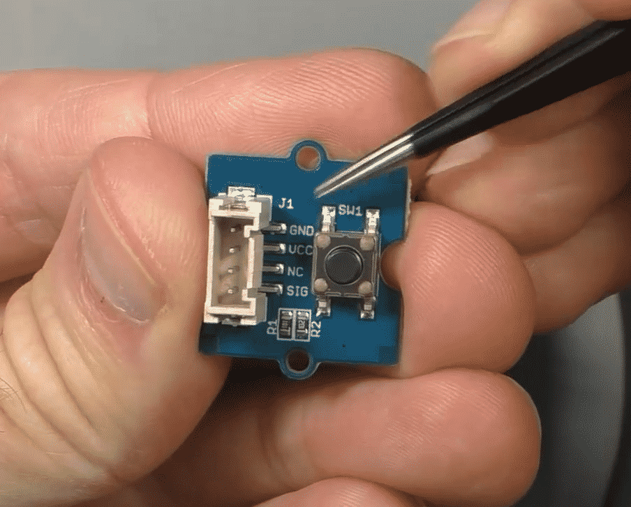
This module contains a momentary button with its pull-down resistor. Plug it into a Grove connector and it's ready to use.
This is a Seeed product. Click on the red button, to complete your purchase on the Seeed website.

About this experiment
I'll show you how to use this button module in the simplest way possible. I am not going to do anything fancy, because I believe that simplicity is the key for good learning.
For more elaborate experiments and examples, have a look at the 5 projects in Grove For Busy People.
In this article, you will learn how to connect a Grove button to your Arduino via the Grove Base Shield, and take readings from it.
Let's begin.
About the Grove button
The button, as you probably already know, is a digital device. Since the button can be either pressed or not pressed, it has only two possible states. These states are translated to voltage (high or low), and the Arduino with your sketch will then translate this voltage into a logical value.
Because the Grove button module has an on-board pull-down resistor, when the button is not pressed, the signal voltage of the button is GND. When the button is pressed, then the signal voltage will be 5V (if you are working with a regular Arduino Uno). If you are working with a Seeeduino and have set its power switch to 3.3V, then the pressed button signal level will be 3.3V.
Still considering the Grove button module, when the button is not pressed, your sketch will perceive its value as a logical "LOW" or "0". When the button is pressed, your sketch will perceive the same as a "HIGH" or "1".
Connect the Grove button
Let's connect the Grove button module to one of the Grove connectors on the Base Shield.
Take a Grove cable.
Plug one end in socket D4 on the Grove Base Shield.
Plug the other end in the Grove socket of the button module.
There is no way to make a mistake here 🙂
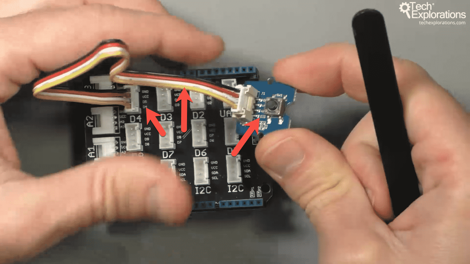
Your circuit should look like the example in this photo:

This button is connected to Arduino digital pin 4, using the Grove connector D4.
The arrows in the photo above show the pins involved. On the button module, the pin marked "SIG" is the one that conveys the state of the button to the Arduino. It is the first pin from the left.
Follow the yellow wire of the Grove cable to see where it ends up in the Base Shield. The left-most red arrow points to D4. This is the Arduino digital pin 4. This pin happens to be broken out in the Grove connector D4 (noted in large text on the Base Shield).
Be careful: There are two "D4" on the Base Shield. But, one refers to the Arduino pin, while the other refers to the Grove connector.
Now that we know which Arduino pin the button is connected to, we can move on to the sketch.
The Arduino sketch
The sketch we'll use to read the state of the button is very simple.
1 2 3 4 5 6 7 8 9 10 11 12 13 14 15 16 17 18 19 20 21 22 23 24 25 26 27 28 29 30 31 32 33 34 35 36 37 38 39 40 41 42 43 44 45 46 47 48 49 50 51 52 53 54 55 56 57 58 59 60 61 62 63 64 65 66 67 68 69 70 71 72 73 74 |
/* 03.020 - Grove momentary button * This sketch demonstrates how to use the Grove momentary button. The momentary button is a digital device (i.e. it can be "on" or "off" only). Components ---------- - Grove Base Shield - An Arduino Uno compatible board (such as Arduino/Genuino Uno or Seeeduino) - Grove momentary button - One Grove cable IDE --- Arduino IDE Libraries --------- - Connections ----------- Use a Grove cable to connect the temperature module to Base Shield connector D2. Other information ----------------- - Use this sketch along side the video lecture 03.020 of Grove For Busy People - Original example sketch location: http://wiki.seeedstudio.com/Grove-Button/ - Grove component: https://txplo.re/a8cb6 Github Gist ----------- <script src="https://gist.github.com/futureshocked/d53f230adbc249b3a59571575459f1a2.js"></script> https://gist.github.com/futureshocked/d53f230adbc249b3a59571575459f1a2 For course information, please go to https://techexplorations.com/product/grove-for-busy-people/ Created on July 5 2019 by Peter Dalmaris */ // constants won't change. They're used here to set pin numbers: const int buttonPin = 4; // digital pin 4 is on Grove connector D4 const int ledPin = 13; // the number of the build-in LED pin // variables will change: int buttonState = 0; // variable for reading the pushbutton status void setup() { // initialize the LED pin as an output: pinMode(ledPin, OUTPUT); // initialize the pushbutton pin as an input: pinMode(buttonPin, INPUT); } void loop() { // read the state of the pushbutton value: buttonState = digitalRead(buttonPin); // check if the pushbutton is pressed. If it is, the buttonState is HIGH: if (buttonState == HIGH) { // turn LED on: digitalWrite(ledPin, HIGH); } else { // turn LED off: digitalWrite(ledPin, LOW); } } |
There is nothing fancy in this sketch; it should be familiar to you if you have done any work with the Arduino.
In line 49, I set the button pin.
It is set to pin 4, which is the Arduino digital pin D4.
In line 50, I also set the pin for the build-in LED: 13.
Reading the state of the LED works with the regular "digitalRead" function, and changing the state of the LED works with "digitalWrite".
Execute the sketch
Upload the sketch to your Arduino, and press the button on the Grove module.
The build-in LED will turn on, as expected.
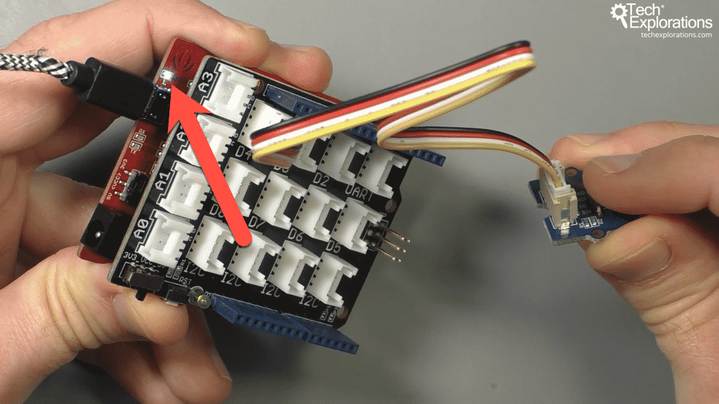
In the photograph below, I use a Seeeduino. When I press the momentary button module, the blue LED connected to digital pin 13 turns on.

Press the button to turn on the LED.
How easy was that? Wiring literally takes 10 seconds or less, with zero risk of error, and no need to use a pull-down resistor.
Ready for another experiment? Let's try out an analog module in the next article.

Ready for some serious learning?
Enrol to
Grove For Busy People
In this course, I’m going to show you how to use the Grove system for the Arduino.
It is a course for people who know the basics of the Arduino. If you have never used an Arduino before, consider enrolling to Arduino Step by Step Getting Started first.
Just click on the big red button to learn more.
Last Updated 1 year ago.
We publish fresh content each week. Read how-to's on Arduino, ESP32, KiCad, Node-RED, drones and more. Listen to interviews. Learn about new tech with our comprehensive reviews. Get discount offers for our courses and books. Interact with our community. One email per week, no spam; unsubscribe at any time
