Getting Started with Grove guide series
Experiment: LED module
In this article, I'll show you how to use a Grove LED module. Wiring will need only a few seconds and has not risk of error.

In this article, I'll show you how to use a Grove LED module. Just like with the button module, wiring will need only a few seconds and has not risk of error.
If you prefer to watch the video version of this article, go ahead.
Purchase a Grove LED module
This module has a socket for a 5mm LED, and a potentiometer that controls brightness.
This is a Seeed product. Click on the red button, to complete your purchase on the Seeed website.

About this experiment
I'll show you how to use this LED module.
Let's begin.
About the Grove LED module
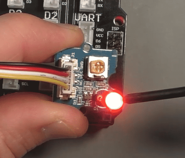
The LED module contains a socket in which you can insert the pins of a 5mm LED. Take an LED, determine which pin is the anode (it's the one that is longer), and insert the anode in the socket marked "+".
The LED module also contains a potentiometer. This potentiometer controls the brightness of the LED.
Connect the Grove LED module
Let's connect the LED module to one of the Grove connectors on the Base Shield. Because this module is a digital device, we'll use one of the available digital Grove connectors
Take a Grove cable.
Plug one end in socket D4 on the Grove Base Shield.
Plug the other end in the Grove socket of the LED module.
Done 🙂
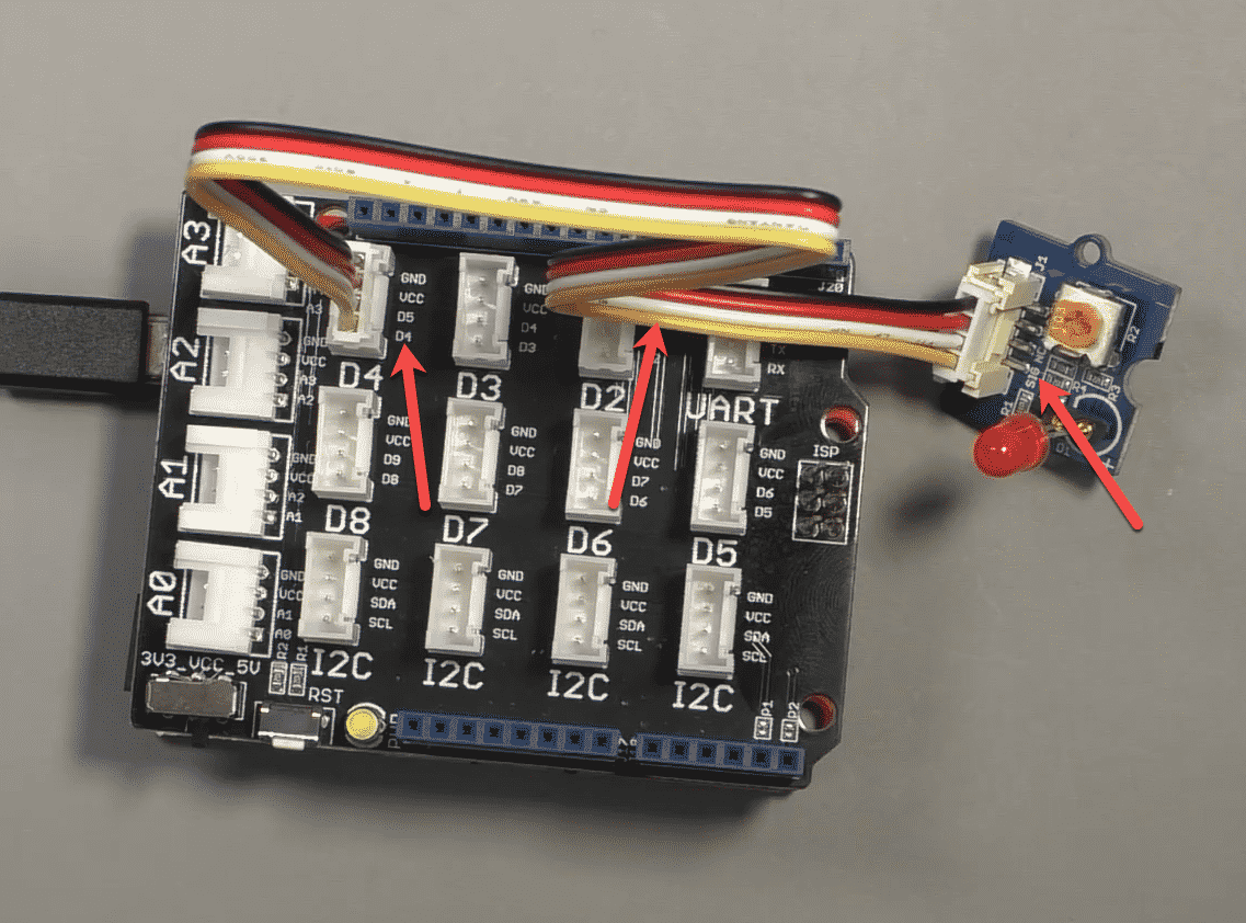
Your circuit should look like the example in this photo:

The LED module is connected to Arduino digital pin 4
As we did with the button, follow the yellow wire from the module pin "SIG" to the Base Shield to determine the Arduino pin we will need to use in the sketch.
In the photograph, the arrows point to the yellow wire that conveys the controlling signal, and the two pins it connects: Arduino digital pin 4 (D4) which is in Grove connector D4, and pin "SIG" on the module.
Now that we now which Arduino pin the module is connected to, we can continue with the sketch.
The Arduino sketch
The sketch we'll use to read the state of the temperature sensor and calculate the temperature in degrees Celsius is very simple.
Have a look:
1 2 3 4 5 6 7 8 9 10 11 12 13 14 15 16 17 18 19 20 21 22 23 24 25 26 27 28 29 30 31 32 33 34 35 36 37 38 39 40 41 42 43 44 45 46 47 48 49 50 51 52 53 54 55 56 57 58 59 60 61 62 63 64 65 66 67 68 |
/* 05.010 - Grove LED module * This sketch demonstrates how to use the Grove LED kit. This module contains a header in which you can attach an LED. Take care to connect the anode (long pin) of the LED into the socket marked with "+". The cathode should go to the socket marked with "-". You can use a Phillips screwdriver to adjust the brightens by turning the on-board potentiometer. Components ---------- - Grove Base Shield - An Arduino Uno compatible board (such as Arduino/Genuino Uno or Seeeduino) - Grove LED kit module - An LED - One Grove cable IDE --- Arduino IDE Libraries --------- - Connections ----------- Use a Grove cable to connect the module to Base Shield connector D4. Other information ----------------- - Use this sketch along side the video lecture 05.010 of Grove For Busy People - Grove component: https://txplo.re/afed7 Github Gist ----------- <script src="https://gist.github.com/futureshocked/b1f667b02361d4a38d40938523ef71c9.js"></script> https://gist.github.com/futureshocked/b1f667b02361d4a38d40938523ef71c9 For course information, please go to https://techexplorations.com/product/grove-for-busy-people/ Created on July 5 2019 by Peter Dalmaris */ const int ledPin = 4; // Connect the LED to Arduino digital pin 4 void setup() { // initialize ledPin as an output. pinMode(ledPin, OUTPUT); } // the loop function runs over and over again forever void loop() { digitalWrite(ledPin, HIGH); // turn the LED on (HIGH is the voltage level) delay(1000); // wait for a second digitalWrite(ledPin, LOW); // turn the LED off by making the voltage LOW delay(1000); // wait for a second } |
In line 54, we set the LED controlling pin, which is Arduino digital pin 4 (as we determined during the wiring process).
Inside the loop, using the "digitalWrite" function, we simply write the "HIGH" value to turn on the LED, and the "LOW" value to turn it off.
Let's try out this sketch and circuit.
Execute the sketch
Upload the sketch to your Arduino. The LED will blink on and off every one second.
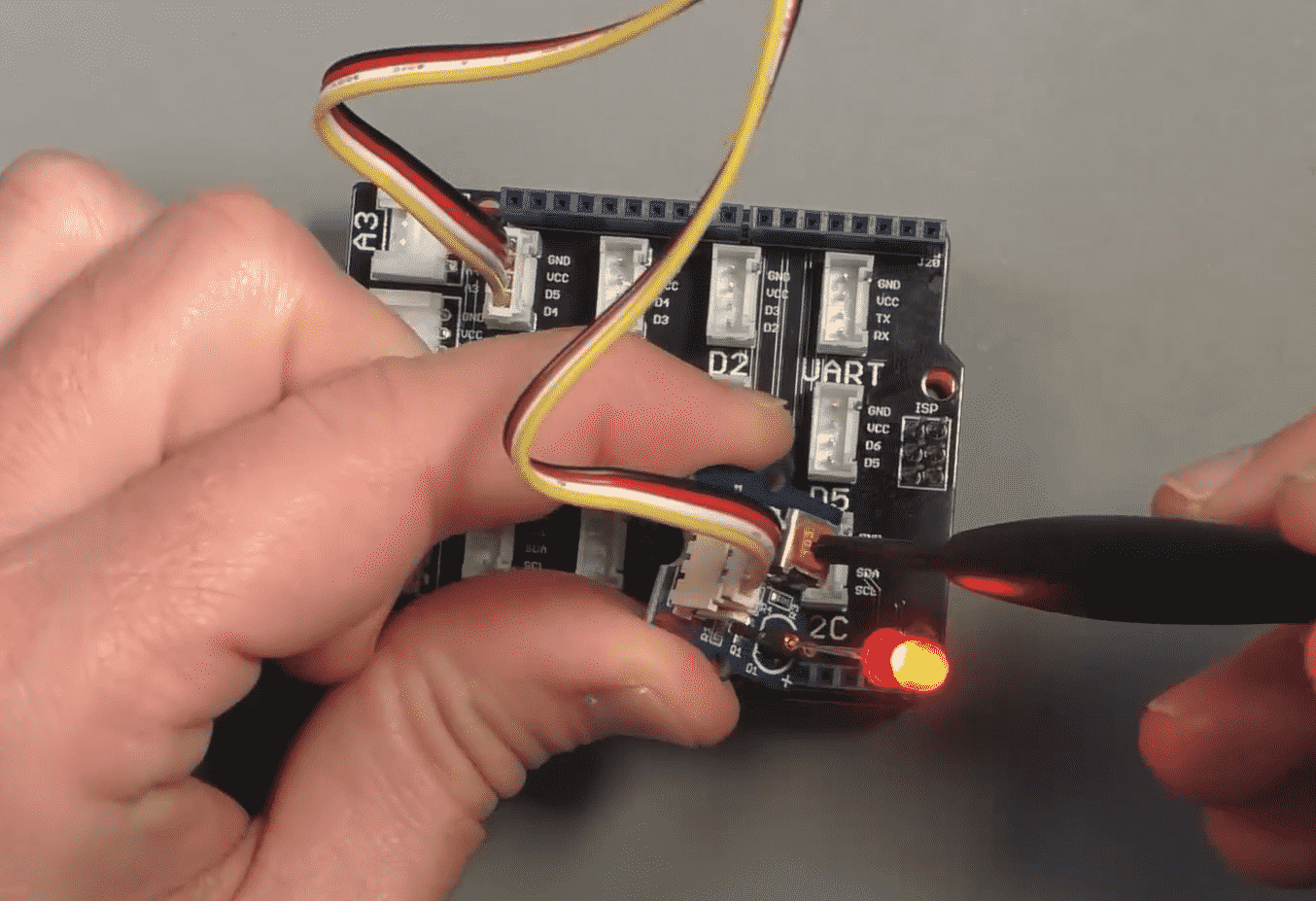
Use a screwdriver to control the brightness of the LED.

Use a screwdriver and the on-board potentiometer to calibrate the brightness of the LED.
How easy was that?
A few seconds to do the wiring, and then straight to the programming part of the prototyping process. The LED module contains a current limiting resistor and a potentiometer and supporting electronics. If you wanted to put all that on a breadboard, just getting this LED to blink would have taken a lot more time.
If you're interested in learning how to use more Grove modules, and in particular how to make them work together through 5 fun projects, I invite you to have a look at my course Grove for Busy People.
Enjoy!

Ready for some serious learning?
Enrol to
Grove For Busy People
In this course, I’m going to show you how to use the Grove system for the Arduino.
It is a course for people who know the basics of the Arduino. If you have never used an Arduino before, consider enrolling to Arduino Step by Step Getting Started first.
Just click on the big red button to learn more.
Looking for useful Grove resources?
Last Updated 1 year ago.
We publish fresh content each week. Read how-to's on Arduino, ESP32, KiCad, Node-RED, drones and more. Listen to interviews. Learn about new tech with our comprehensive reviews. Get discount offers for our courses and books. Interact with our community. One email per week, no spam; unsubscribe at any time
