Getting Started with Grove guide series
Experiment: Analog temperature sensor module
In this article, I'll show you how to use a Grove analog temperature sensor module. As you'll see, wiring will be a breeze and error-free.

In this article, I'll show you how to use a Grove analog temperature sensor module. As you'll see, just like with the button module, wiring will be a breeze and error-free.
If you prefer to watch the video version of this article, go ahead.
Purchase a Grove Temperature module
This module contains a thermistor. Plug it into a Grove analog connector and it's ready to measure temperatures between -40 to 125°C , with an accuracy of 1.5°C.
This is a Seeed product. Click on the red button, to complete your purchase on the Seeed website.

About this experiment
I'll show you how to use this temperature module to measure temperature.
Let's begin.
About the Grove temperature module
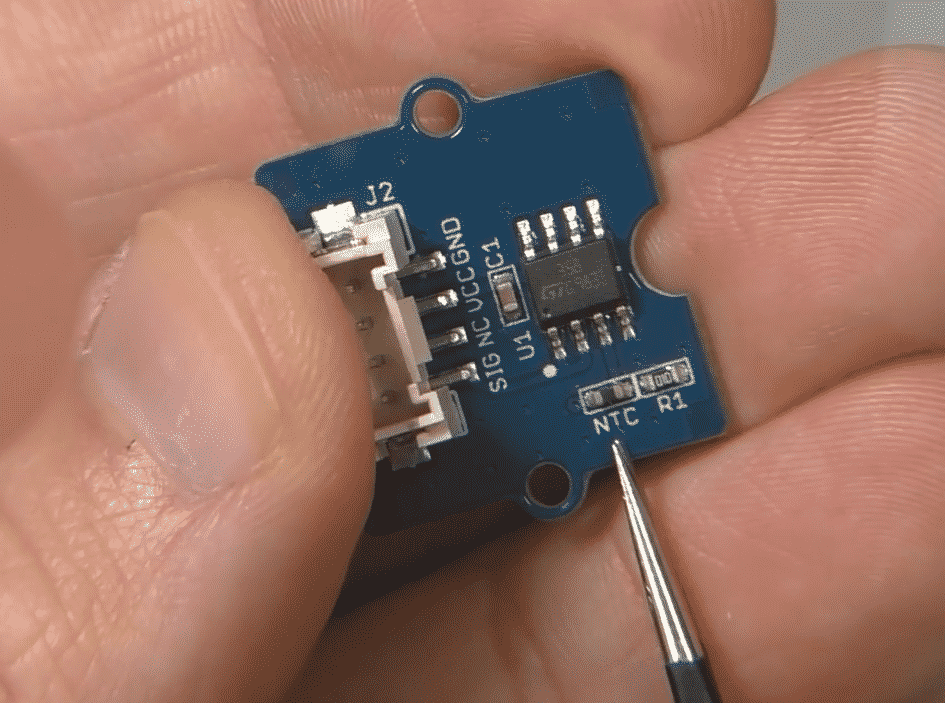
This module contains a thermistor, model NCP18WF104F03RC, which is a variable resistor.
The value of the resistance depends on the ambient temperature.
The module uses an NTC thermistor. NTC stands for "Negative Temperature Coefficient". This means that when the temperature of the component increases, its resistance decreases, and vice-versa.
Connect the Grove temperature module
Let's connect the temperature module to one of the Grove connectors on the Base Shield. Because this module is an analog device, we'll use one of the available analog Grove ports, instead of the digital ones we used in the button experiment.
Take a Grove cable.
Plug one end in socket A0 on the Grove Base Shield.
Plug the other end in the Grove socket of the temperature module.
Done 🙂
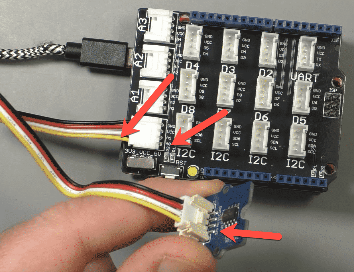
Your circuit should look like the example in this photo:

The SIG pin of the module is connected to Arduino A0.
As we did with the button, follow the yellow wire from the module pin "SIG" to the Base Shield to determine the Arduino pin we will need to use in the sketch.
In the photograph, the arrows point to the yellow wire that conveys the temperature module signal, and the two pins it connects: Arduino analog pin 0 (A0) which is in Grove connector A0, and pin "SIG" on the module.
Now that we now which Arduino pin the module is connected to, we can continue with the sketch.
The Arduino sketch
The sketch we'll use to read the state of the temperature sensor and calculate the temperature in degrees Celsius is very simple.
Have a look:
1 2 3 4 5 6 7 8 9 10 11 12 13 14 15 16 17 18 19 20 21 22 23 24 25 26 27 28 29 30 31 32 33 34 35 36 37 38 39 40 41 42 43 44 45 46 47 48 49 50 51 52 53 54 55 56 57 58 59 60 61 62 63 64 65 66 67 68 69 70 71 72 73 74 75 |
/* 04.010 - Grove temperature sensor (Temperature Sensor V1.1/1.2) * This sketch read the voltage of a Grove temperature sensor and calculates the temperature in degrees C. The temperature sensor is an analog sensor. Components ---------- - Grove Base Shield - An Arduino Uno compatible board (such as Arduino/Genuino Uno or Seeeduino) - Grove Temperature Sensor V1.1/1.2 - One Grove cable IDE --- Arduino IDE Libraries --------- - Math Connections ----------- Use a Grove cable to connect the temperature module to Base Shield connector A0. Other information ----------------- - Use this sketch along side the video lecture 04.010 of Grove For Busy People - Original sketch location: http://wiki.seeedstudio.com/Grove-Temperature_Sensor_V1.2/ by Loovee @ 2015-8-26 - Grove component: https://txplo.re/4hc - Thermistor datasheet: http://www.mwftr.com/emblab/Temp%20Sensor%20-NCP18WF104F03RC.pdf - Thermistor model: NCP18WF104F03RC (NTC- Negative Temperature Coefficient) - Learn about temperature coefficient: https://en.wikipedia.org/wiki/Temperature_coefficient Github Gist ----------- <script src="https://gist.github.com/futureshocked/79960bb8bebaa0ff5b1a4c7534a805e1.js"></script> https://gist.github.com/futureshocked/79960bb8bebaa0ff5b1a4c7534a805e1 For course information, please go to https://techexplorations.com/product/grove-for-busy-people/ Created on July 5 2019 by Peter Dalmaris */ #include <math.h> const int B = 4275; // B value of the thermistor const int R0 = 100000; // R0 = 100k const int pinTempSensor = A0; // Grove - Temperature Sensor connect to A0 void setup() { Serial.begin(9600); } void loop() { int a = analogRead(pinTempSensor); float R = 1023.0/a-1.0; R = R0*R; float temperature = 1.0/(log(R/R0)/B+1/298.15)-273.15; // convert to temperature via datasheet Serial.print("temperature = "); Serial.println(temperature); delay(100); } |
In the sketch, we include the math library because we need to do a couple of calculations, one of which is a logarithm. The function for the logarithm calculation exists in the math C library.
In line 55, we set the B coefficient, which depends on the thermistor module, and can be found in its datasheet.
In line 56, we set the fix voltage divider resistor. The temperature module contains a 100KΩ resistor.
Both these values are needed for the temperature calculation in the loop.
In line 57, we set the signal pin of the temperature module. We have connected the module to Arduino analog pin 0, or "A0".
Inside the loop, we calculate the temperature in degrees Celsius by breaking down the formula in three parts, and working out a couple of intermediate results.
Let's try out this sketch and circuit.
Execute the sketch
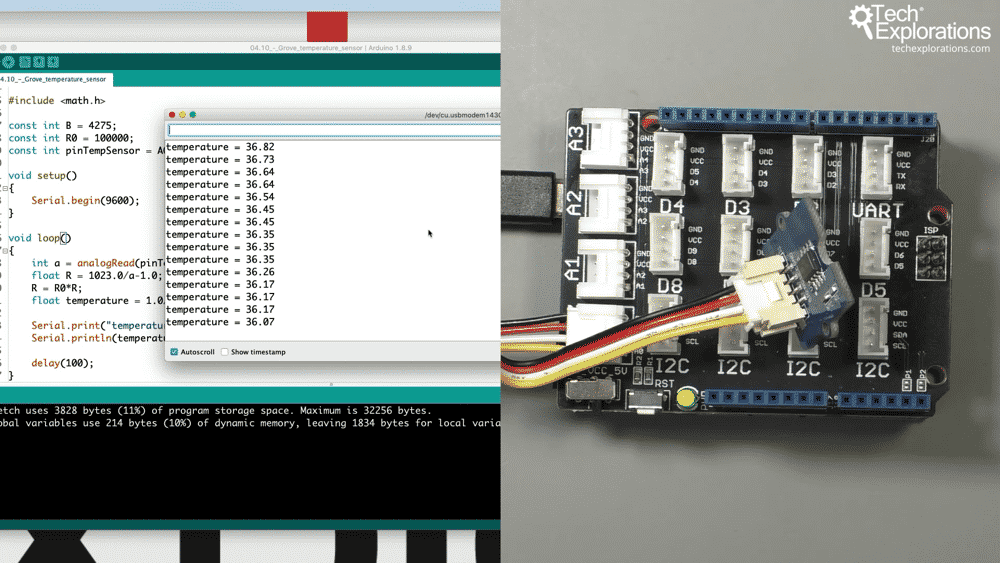
Upload the sketch to your Arduino. To increase the temperature on the sensor, I used a heat gun.
Start the serial monitor to see the calculated temperature.
Every 100 milliseconds, a new temperature will be printed.

The calculated temperature is printed in the serial monitor.
Again, how easy was that? Wiring literally takes 10 seconds or less, just like with the button experiment. There was zero risk of error, and no need to use a fixed resistor for the voltage divider. The module even contains a signal amplifier which helps to provide a more reliable measurement.
Let's try out one more experiment in this series. In the next article, I'll show you how to control an LED.

Ready for some serious learning?
Enrol to
Grove For Busy People
In this course, I’m going to show you how to use the Grove system for the Arduino.
It is a course for people who know the basics of the Arduino. If you have never used an Arduino before, consider enrolling to Arduino Step by Step Getting Started first.
Just click on the big red button to learn more.
Looking for useful Grove resources?
Last Updated 1 year ago.
We publish fresh content each week. Read how-to's on Arduino, ESP32, KiCad, Node-RED, drones and more. Listen to interviews. Learn about new tech with our comprehensive reviews. Get discount offers for our courses and books. Interact with our community. One email per week, no spam; unsubscribe at any time
