Data Acquisition and Control guide series
10
Potentiometer with AIO
In this lesson, I show how to use a potentiometer with the LabJack T4.
-00-01-53-004")
Hi, thanks for stopping by! Just letting you know that we are currently working on this page. You may notice incorrect links and lots of typos. We expect to buff and polish within a few days.
In this lesson, I have replaced the button that we saw in the previous lesson with a potentiometer. I will compare the voltage read by the LabJack on AIN0 with what the value measured by my digital multimeter.
So, I have connected to the probes of the multimeter on the GND and VS pins as those broken out via the jumper wires onto the breadboard and on the potentiometer. So, they will give us an indication of what kind of volts we're getting against what my multimeter is showing.
Wiring
-00-00-33-118")
A 10KΩ potentiometer is connected to the AIN0 port of a LabJack T4.
To connect the 10KΩ potentiometer to the LabJack, follow these instructions (top-bottom reference according to the image above):
-
1Connect the middle pin of the potentiometer to AIN0 (yellow wire).
-
2Connect the top pin of the potentiometer to VS (red wire).
-
3Connect the bottom pin of the potentiometer to GND (black wire).
In the image above you can see the black and red probes of my multimeter. Black is connected to the grounded pin of the potentiometer, and red is connected to the middle pin (signal) of the potentiometer.
Let's take some measurements.
Measurements
-00-01-31-731")
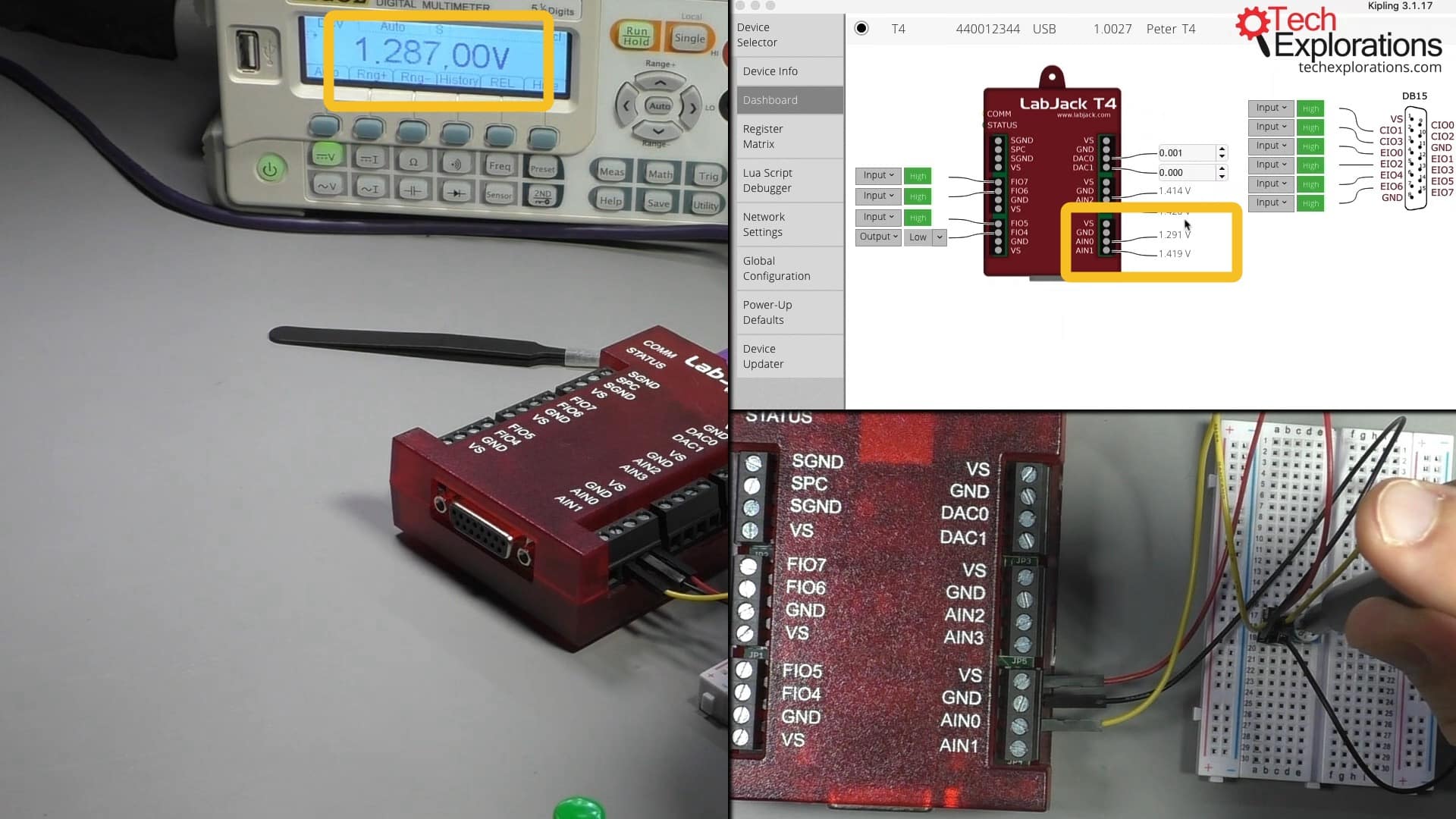
Composite view showing the the potentiometer voltage on the multimeter and Kipling's Dashboard.
Let's have a look at the voltage that the potentiometer is producing as it is measured by LabJack on AIN0. For this, we'll use the Dashboard view in Kipling.
At the current position of the potentiometer, the voltage on AIN0 is 1.29V. The multimeter is showing a similar value at 1.287V.
Let's change the position of the potentiometer with a flat head screw driver and see how the voltage changes. Go between the two edges; I find that at the lower edge the voltage goes down to 0.1V, whereas at the top edge it goes up to 4.8V.
-00-02-42-989")
Edit your caption text here
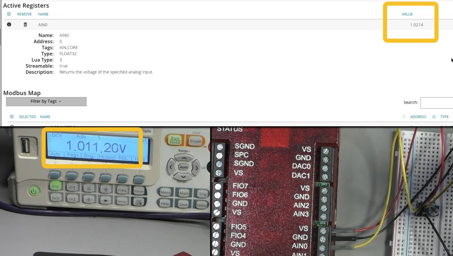
You can get the same information from the Registers Matrix, as in the example in the screenshot above.
This simple experiment concludes this series of articles. Would you like to learn more about the LabJack data acquisition devices? Consider enrolling to our comprehensive video course.
"Data Acquisition and Control" series
Learn Data Acquisition and Control with LabJack
With this video course, you will learn how to use the LabJack device to perform data acquisition and control (DaQ) operations.
LabJack was designed to be robust and reliable, to work autonomously in harsh environments for a long period of time, and to have a lot of input/output ports able to connect to a huge range of sensors and actuators.
Jump to another article
We publish fresh content each week. Read how-to's on Arduino, ESP32, KiCad, Node-RED, drones and more. Listen to interviews. Learn about new tech with our comprehensive reviews. Get discount offers for our courses and books. Interact with our community. One email per week, no spam; unsubscribe at any time