Oscilloscopes For Busy People guide series
Probes
In this article, I discuss the device that allows you to connect a circuit to your oscilloscope so that you can take measurements.

In this article, I discuss the device that allows you to connect a circuit to your oscilloscope so that you can take measurements.
We’ll have a look at the types of probes that are available, their most important specifications, and how to use them. Probes is a big topic on its own. In this lecture I am only covering the basic and most important concepts.
Your oscilloscope must be physically connected to your test circuit in order to make a measurements. This happens via a test probe. A probe is a device that conveys the signal to be measured from the test circuit to the oscilloscope.
Naturally, we want our measurements to be as accurate as possible, and therefore the probe is important to not modify the original signal in any way. Or at least, if it does modify it is some way, it should be done in a controllable and predictable way.
A passive probe, annotated.
In this image, you can see one of my probes. Let’s have a look at the parts that make up this probe.
At one end, on the left, you can see the probe tip. The tip comes in a few different types, like a hook (the type I use in this course), a point (I’ll show you an example shortly), or a spring. The tip is the part of the probe that we attached to the location of a circuit from where we want to take a measurement.
In the middle of this photo you can see the ground lead. The ground lead is physically attached to the handle of the probe, and usually is made up of a crocodile clip. We attach the clip to an appropriate ground point to provide a voltage reference for our measurement.
On the right of this photo, you can see the input connector. This is how we connect the probe to the oscilloscope. The connector comes in a variety of types. The one in this photo is a BNC connector, which is more common. There are also SMA connectors, similar to those used to connect an antenna to a radio modem.
The BNC input connector is attached to a small black box. In the back of this box is an opening that gives access to a screw. This is the compensation screw that allows us to improve the electrical characteristics of the probe so that it can convey a better signal from the test circuit to the oscilloscope. Hold on to that thought for now, I will talk more about attenuation in a minute.
Also notable in this photo are my stickers, and the identifier ring. I use stickers to clearly mark the role of a probe so that I don’t make silly mistakes when I connect them to my circuit.
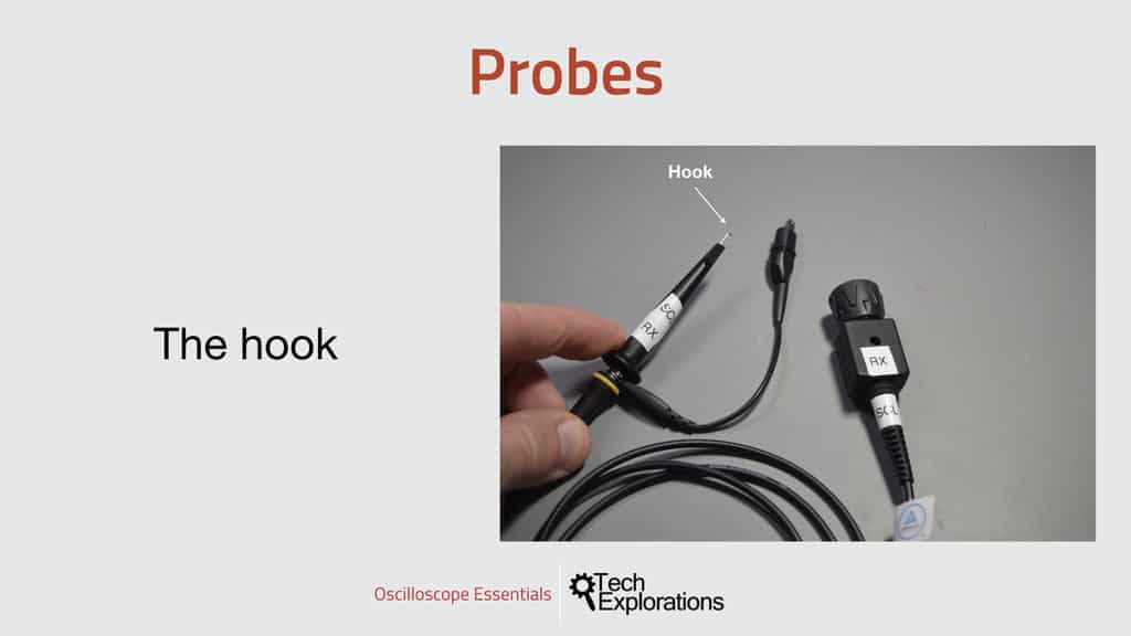
The hook
In this photo you can see the hook.

The hook is the most common mechanism for attaching the probe to a circuit.
The hook is contained inside a spring-loaded cover. Pull the cover down to expose the hook, and attach the hook to a wire or pin that you want to use as input. Then release the cover to reduce the amount of metal that is exposed, and secure the connection.
I’ll be using the hook in the experiments in Oscilloscopes for Busy People because it is quick to snap on the circuit, and once is connected I don’t have to continue to hold on to the probe.
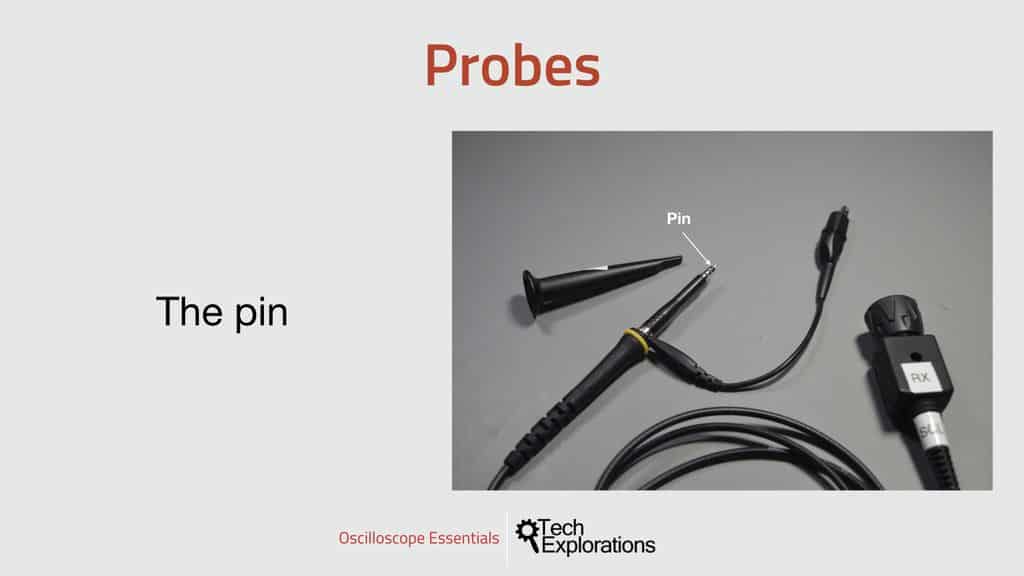
The pin
If you need to measure a signal available through a really small surface, like a pad of an SMD component, you can use the pin. Expose the pin by removing the hook assembly.

Most probes contain a pin under the hook cover.
In my probe, I can turn the hook assembly as if it was a screen to release it from the handle.
The pin allows you to connect the probe to very small places, by it’s not a hands-free operation: you’ll have to hold it in place.
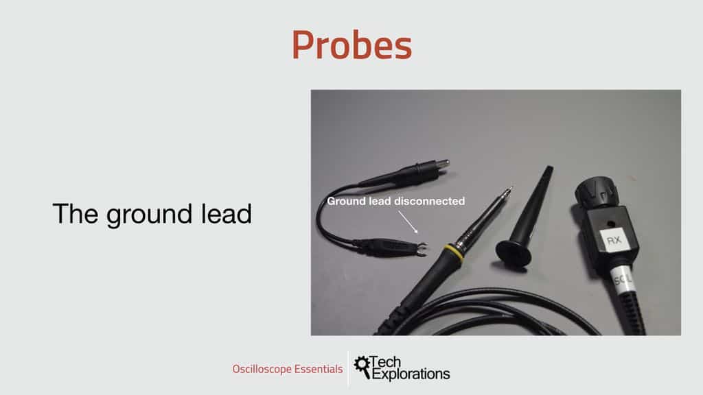
The ground lead
In most probes, you can disconnect the ground lead and replace it with a different type. Perhaps you need a different way for the lead to latch on a ground source such as a spring, or a longer lead. Most probes make is easy to interchange these parts.

The ground lead is usually detachable.
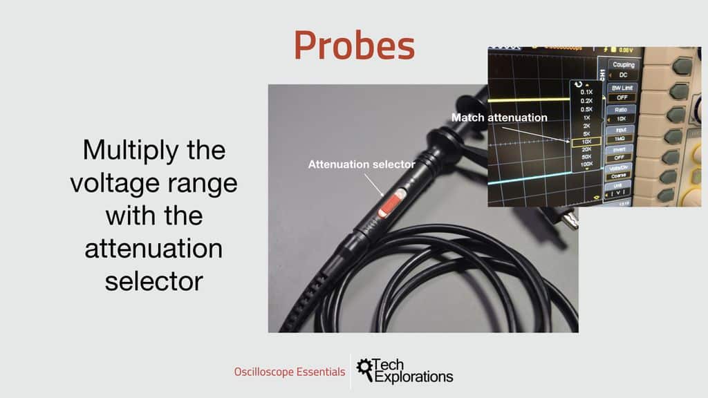
Attenuation selector
Some probes include a switch on their handle. This is the attenuation selector. This switch allows you to change the range of the input voltage that the probe, and as an extension the oscilloscope, can work with.
For example, imagine that your oscilloscope is only rated to be able to safely measure signals from -5V to +5V.
If you use a 1X attenuation probe, then you must ensure that the part of the test circuit that you connect your probe to stays within this range.
But, what if you want to measure a signal that goes up to 20V?

This switch allows you to change the range of the input voltage that the probe
Just flip the red switch to 10X, and your oscilloscope can now (safely) measure a signal of up to 5V x 10 = 50V.
To make this work, you must also set the ratio or attenuation setting on the oscilloscope to match the value of the switch on the probe.
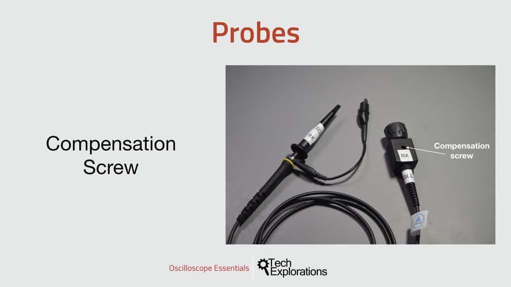
Compensation screw
Let’s return to the reason of the existence of the compensation screw which I mentioned earlier.

By turning the compensation screw, we can achieve a better signal on the oscilloscope
The casing where the input connector is attached contains an RC network. We can adjust the properties of this RC network so that we can achieve a constant attenuation over the probe’s full bandwidth. In simple words, by turning the compensation screw, we can achieve a better signal on the oscilloscope.
A quick reminder here: attenuation is the effect the resistance and capacitance have over the strength of a signal.
Because a probe has both resistance and capacitance, the signal that flows through it is attenuated, that is, it looses some of its strength by the time it gets to the oscilloscope. As long as this attenuation is constant across the full bandwidth of the probe, that’s no problem. But if it isn’t, then we end up with a signal that is weakened at different rates across the bandwidth, and that is not ok as we end up with a signal in the oscilloscope that is very different to the original. This is why we need to compensate the attenuation before we start using the probe.
I’ll show you how to do this in the next section.
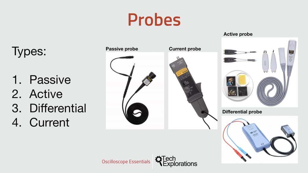
Types of probes
There are several different types of oscilloscope probes: Passive, active, differential, and current.
In Oscilloscopes for Busy People, I’ll be using the passive probes that came with my oscilloscope. Nothing fancy, and great to work with all the typical circuits, like low speed electronics, voltages around 5V that microcontrollers work around and digital communications.

There are many kinds of probes.
A passive probe contains only passive components, like resistors and capacitors and usually an attenuation compensation circuit. They are cheap, and excellent for general purpose measurements.
Active probes contain active components, like amplifiers. They are better at measuring very small and weak signals, or high-speed signals, say above 500MHz.
Finally, differential probes are designed to measure the difference between two signals instead of their absolute values. They are typically used to measure high-frequency signals or signals with very low amplitude.
I also want to make a mention to current probes. A current probe allows us to measure current instead of voltage, using a Hall-effect sensor that can measure the magnetic field that is generated by a DC current as it passes through the probes ferrite core.

Ready for some serious learning?
Enrol to
Oscilloscopes for Busy People
Demystify the oscilloscope and learn how to use it in your projects.
This course is perfect for people who have never used an oscilloscope.
Through a series of projects, this course will teach you how to use an oscilloscope to measure and decode signals in your electronics.
Just click on the big red button to learn more.
Last Updated 1 year ago.
We publish fresh content each week. Read how-to's on Arduino, ESP32, KiCad, Node-RED, drones and more. Listen to interviews. Learn about new tech with our comprehensive reviews. Get discount offers for our courses and books. Interact with our community. One email per week, no spam; unsubscribe at any time