Oscilloscopes For Busy People guide series
Oscilloscope specifications
With this article, you will learn the meaning of the most important specifications of an oscilloscope in a simple and practical way.

With this article, you will learn the meaning of the most important specifications of an oscilloscope in a simple and practical way.
The technical specifications of an oscilloscope can easily fill several pages in table format. Similar to when you are looking for a new car or a new computer, you should focus on what is important first, because the details matter a lot less. Your objective is to find an oscilloscope that fits your budget, and allows you to measure the things that you want to measure.

Oscilloscope specifications can be daunting
Bandwidth
Probably the most important specification of an oscilloscope is its bandwidth. The bandwidth of the the scope governs the maximum frequency of the signal that it can capture and analyse.
As the frequency of the signal gets closer to the maximum frequency that the oscilloscope can work with, its accuracy drops.

The bandwidth of the the scope governs the maximum frequency of the signal that it can capture and analyse
To figure out what bandwidth your oscilloscope should be, use the rule of 5:
"figure out what is the highest frequency in a test signal you’d like to measure, and multiply it by 5."
That’s your oscilloscope bandwidth.
For example, if you want to work with an at its’ maximum 20MhZ clock speed, you will need an oscilloscope that is rated at 100MhZ.
Beware though that this is the Arduino internal clock speed. If you want to work with Arduino PWM signals, then their frequency is just 490 Hz. Or if you want to work with I2C communications between an Arduino and a sensor, you will typically work at 100KHz. So, you can see that even at 20Mhz or 50Mhz of bandwidth, your oscilloscope is perfectly capable to work with most of the kind of signals you are likely to encounter.
Sample rate
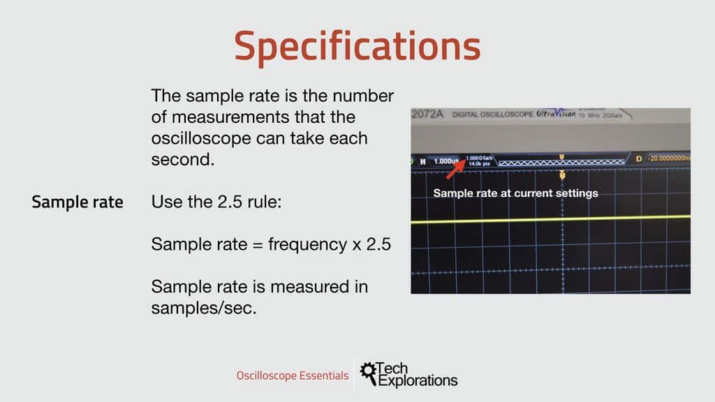
The next important specification of an oscilloscope is its sample rate. The sample rate is the number of samples that the oscilloscope is capable of capturing per second. Obviously, the more, the better. But higher sample rates require more and faster memory to store, and faster electronics and processor to capture and process, driving up the price of the instrument.

The sample rate is the number of samples that the oscilloscope is capable of capturing per second.
As with the bandwidth and other technical decisions we are often called to make, we need to choose an instrument with a sample rate that is good enough for our purposes.
A rule of thumb is to multiply the highest frequency you are likely to encounter in your work with the oscilloscope, and multiply by 2.5.
For example, if you want to work with an I2C signal at 100KHz, multiplying this frequency by 2.5 will give you a sample rate of 250,000 samples per second. Most digital oscilloscopes these days can easily handle this.
Memory size/depth
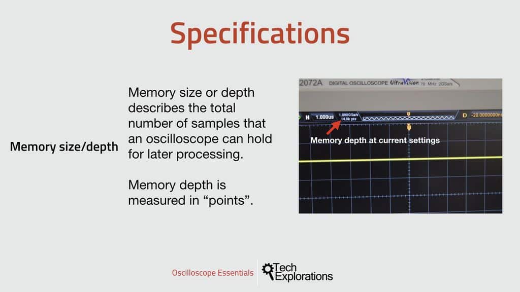
Very closely related to the oscilloscope sample rate is its memory size. As the oscilloscope samples the signal from the test circuit, it stores the waveform data in its memory.
Manufacturers report the memory size of their oscilloscopes using the term “memory depth”, and instead of using the regular byte unit, they use the “points” unit.
An oscilloscope that is quoted to have a memory depth of 54 Mpts can record a total of 54 million samples in its memory. This is divided among the input channels. So, if your oscilloscope has a memory depth of 54 million points, and you are recording on two channels, then each channel will have a memory depth of 54/2 = 28 million points.

Manufacturers report the memory size of their oscilloscopes using the term “memory depth”, and instead of using the regular byte unit, they use the “points” unit.
Of course, memory depth and sample rate go hand in hand. As the sample rate increases, the oscilloscope will need a larger memory to be able to record events that take place within a unit of time.
This about this: Say you want to record a waveform as it changes within 1 second. If your sample rate is 1000 samples per second, then you will need a memory with depth of 1000 points to store all samples. But if your oscilloscope is double as fast and can sample at 2000 samples per second, then you will need a memory depth of 2000 sample to do a full recording for the 1 second event.
Because of the close relation between the sample rate and the memory depth, modern oscilloscopes will automatically manage the sample rate depending on the time scale you have chosen so that the available memory is always filled.
Rise time
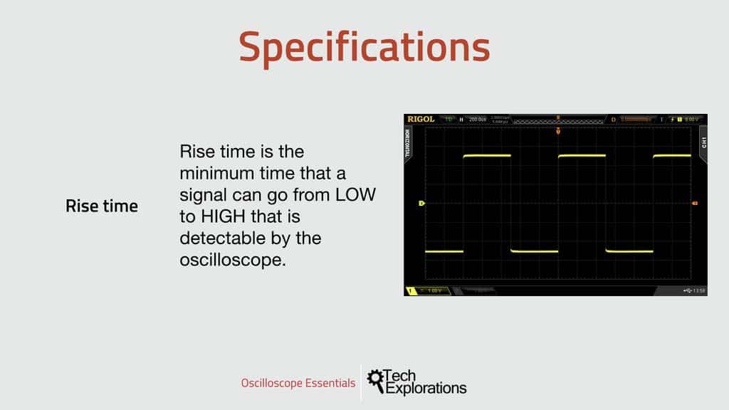
The Rise time of an oscilloscope describes the ability of the instrument to detect and capture rapidly rising and falling signals. This is particularly important when we work with square waves that have very sharp edges. A square wave can rise from 0V to 5V within nanoseconds.

The Rise time of an oscilloscope describes the ability of the instrument to detect and capture rapidly rising and falling signals.
For the oscilloscope to be able to display the waveform of such signal precisely, it must be able to detect such rapid changes.
For example, my oscilloscope has a rise time of 5 nano seconds, which means that the fastest rise time it can detect is 5 nano seconds.
Channels
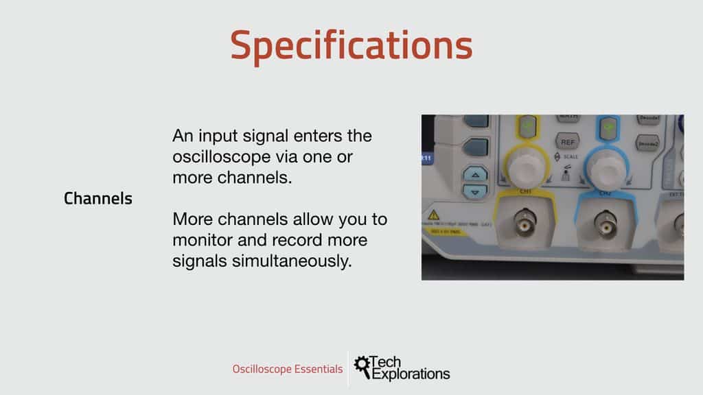
Oscilloscopes typically offer 2 or 4 channels.
Each channel has a separate connector where you can attach a probe, and through this probe to monitor a signal.

Each channel has a separate connector where you can attach a probe, and through this probe to monitor a signal.
An oscilloscope with 2 channels allow you to work with two signals at the same time, and decode data that flow in up to two wires (such as UART serial and I2C).
An oscilloscope with 4 channels allow you to work with up to four signals at the same time, and decode data that flow in up to four wires, such as SPI or a 4-bit parallel bus.
More channels can translate to a need for a larger memory depth and of course cost.
Trigger
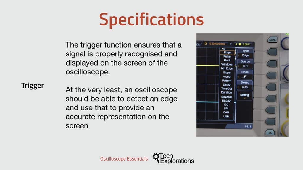
The trigger of an oscilloscope is fundamental to its operation. The trigger is the mechanism through which the oscilloscope can recognise a specific attribute of the input signal. Based on this attribute, the oscilloscope can achieve synchronisation.
You know that the oscilloscope is in synch when the graphical representation of the signal on the screen is clear and stable.
 The trigger is the mechanism through which the oscilloscope can recognise a specific attribute of the input signal.
At the very least, a digital oscilloscope should be able to recognise an edge, upslope or downslope.
But in many cases, oscilloscopes can detect many different kinds of attributes of a signal.
For example, my oscilloscope can detect edges, pulses, and runts, among many others, all of them configurable to very precise specifications. You will be spending a lot of time to configure the trigger before each experiment in this course.

Ready for some serious learning?
Enrol to
Oscilloscopes for Busy People
Demystify the oscilloscope and learn how to use it in your projects.
This course is perfect for people who have never used an oscilloscope.
Through a series of projects, this course will teach you how to use an oscilloscope to measure and decode signals in your electronics.
Just click on the big red button to learn more.
Last Updated 1 year ago.
We publish fresh content each week. Read how-to's on Arduino, ESP32, KiCad, Node-RED, drones and more. Listen to interviews. Learn about new tech with our comprehensive reviews. Get discount offers for our courses and books. Interact with our community. One email per week, no spam; unsubscribe at any time