Motors guide series
Project 1: Control two DC motors with your Arduino and the L298N controller
The L298N motor controller is a low cost and simple way to control two DC motors at the same time. It works well with the Arduino, and once you learn how to use it, you will be able to apply it on a wide range of DC motors.
In this article you will learn how to control two 5V DC motors with your Arduino.
To enable the Arduino to safely control the motors, you will use the L298N motor controller module.
I will be using two geared DC motors from a toy tank that I stole from my kids (they originally stole it from me).
The DC motor controller module
Even though you could connect a small DC motor directly to the Arduino, it is not a good idea.
The Arduino can only provide a very small amount of current to external devices. Only the tiniest of motors would be satisfied with that.
In virtually all real-life applications, you should provide external power to the motor.
To do this, I am going to use a popular motor driver module that contains the L298N motor driver “bridge”. This integrated circuit (IC) can provide enough current to our motors, so we can use them in power-hungry applications. The L298N IC can't be used on its own. It requires several other components to operate properly, such as capacitors and diodes, a heatk sink etc.
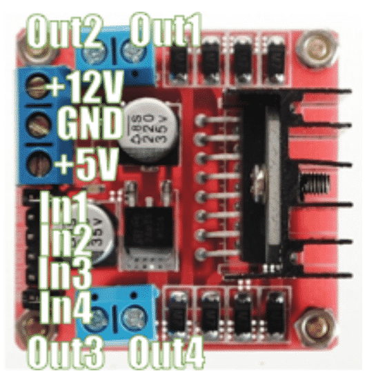
Therefore, it is convenient to use a module that contains the L298N and all of the required components on a single board, like as the one in this image below.
Project parts list
You will need the following components for this circuit:
- Two 5V DC motors.
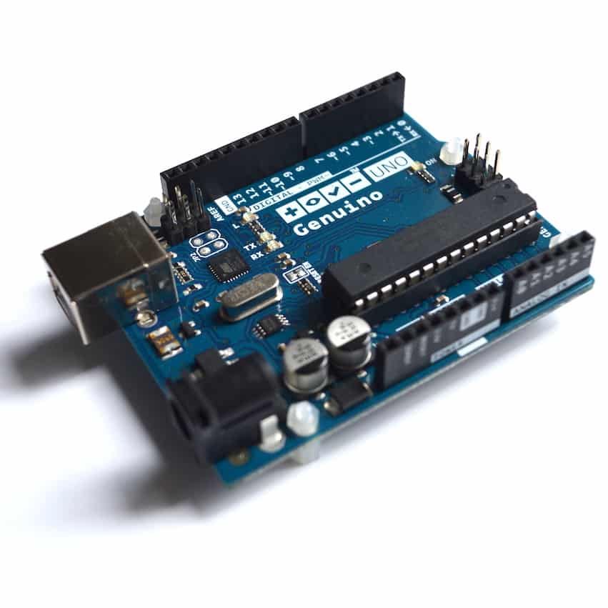
- An Arduino Uno.
- A motor controller module with the L298N chip.
- One AA-battery pack with 4 batteries.
- A bunch of jumper wires.
Circuit assembly process
Follow these instructions to make the connections and build your circuit. Refer to the annotated photograph of the L298N module above for the pin names.
Start by unplugging the Arduino from your computer so that it is not in operation.
- Connect the first motor to motor controller module Out1 and Out2. The order does not matter.
- Connect the first motor to motor controller module Out3 and Out4. The order does not matter.
- Connect the positive wire from the battery pack to pin +12V on the module.
- Connect the negative wire from the battery pack to pin GND on the module.
- Connect the GND pin of the module to the GND pin of the Arduino.
- Connect Arduino pin 5 to module pin In1.
- Connect Arduino pin 4 to module pin In2.
-
Connect Arduino pin 3 to module pin In3.
- Connect Arduino pin 2 to module pin In4.
-
Inspect the wiring and ensure they are correct.
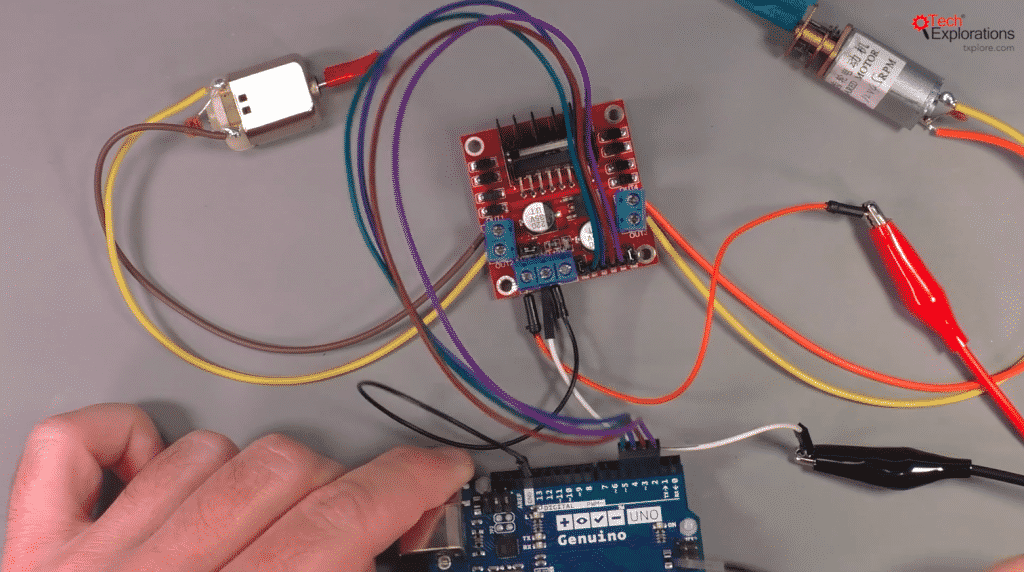
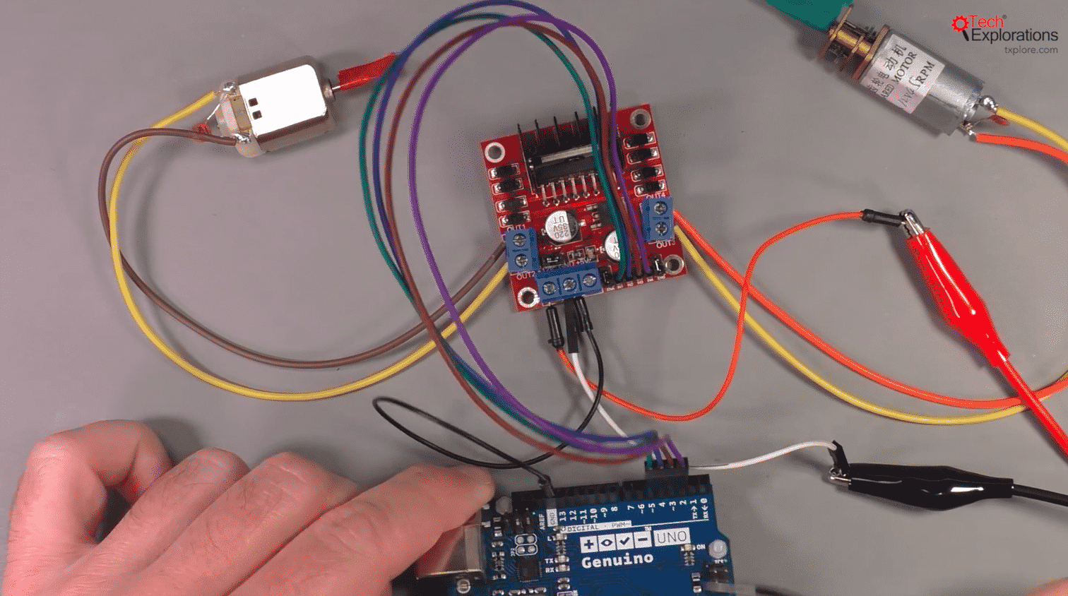
And here’s what the assembled circuit looks like:
Let's look at the role of each pin in the motor controller module.
Out1 and Out2 control the speed and direction of motor 1.
Out3 and Out4 control motor 2.
As we are using DC motors, the higher the voltage differential between the pins in those pairs, the faster the motors will spin. If you want to reverse the motors, you must change the polarity of these pins. This is something that the L298N will do for you with the appropriate signal in the input pins.
In1 and In3 control the direction of spin for motor 1 and motor 2 respectively.
In2 and In4 control the speed for each motor.
Pin "+12V" receives power from an external power source. In this experiment, the safest option is to use an AA battery pack. If you use alkaline batteries, you will have 4 x 1.5V = 6V. This is sufficient to drive our two motors.
Finally, pin "GND" is for ground, and should be connected to one of Arduino’s GND pins so that both the Arduino and the module share the same ground voltage level.
Sketch for project 1
Here’s the sketch for Demo 1:
//Arduino PWM Speed Control:
int E1 = 5;
int M1 = 4;
int E2 = 6;
int M2 = 7;
void setup()
{
pinMode(M1, OUTPUT);
pinMode(M2, OUTPUT);
}
void loop()
{
int value;
for(value = 0 ; value <= 255; value+=1)
{
digitalWrite(M1,HIGH);
digitalWrite(M2,HIGH);
analogWrite(E1, value); //PWM Speed Control
analogWrite(E2, value); //PWM Speed Control
delay(30);
}
}
We start by setting the digital pins for the motor 1 and motor 2 control. We need two pins to control each motor. The “M” pins control the direction of rotation for the motor shafts, and the “E” pins control the speed.
In the setup() function we set the mode for pins M1 and M2 to be output (so we can control the direction of the spin).
In the loop() function, we have a “for” loop that cycles from 0 to 255, so it covers all the possible PWM values that can be written to pins E1 and E2 (Arduino pins 5 and 6 respectively).
Every time that the block in this loop runs, we first set the direction of spin for both motors by writing a HIGH value to pins M1 and M2 (Arduino pins 4 and 7 respectively), and then we set the spin by using the PWM function analogWrite. The value we write to these pins is controlled by the “for” loop.
Once you connect this circuit and run the loop, you will have your motors starting from zero speed, speeding up gradually until they reach their maximum rotational speed, before they suddenly stop to a halt and then repeating the same processes again, until power is switched off.
To change the direction of rotation, just change the value you write to either M1 or M2 pins to LOW, and upload the sketch. You will see the corresponding motor shaft moving the opposite way compared to the original sketch.
Learn more
If you would like to learn how to use DC motors with your Arduino, consider enrolling to Arduino Step by Step Getting Serious.
We have a full section (Section 16) with 10 lectures dedicated to this topic.
New to the Arduino?
Arduino Step by Step Getting Started is our most popular course for beginners.
This course is packed with high-quality video, mini-projects, and everything you need to learn Arduino from the ground up. We'll help you get started and at every step with top-notch instruction and our super-helpful course discussion space.
Jump to another article
2. How to drive a DC motor without a motor driver module
3. What is "microstepping"?
4. Direct current motor
5. Project 1: Control two DC motors with your Arduino and the L298N controller
6. Project 2: Control speed and direction with a potentiometer
7. Project 3: DC motor control with a distance sensor
8. Project 1: Control a servo motor with a potentiometer
9. Project 2: Servo motor control with VarSpeedServo
Done with the basics? Looking for more advanced topics?
Arduino Step by Step Getting Serious is our comprehensive Arduino course for people ready to go to the next level.
Learn about Wi-Fi, BLE and radio, motors (servo, DC and stepper motors with various controllers), LCD, OLED and TFT screens with buttons and touch interfaces, control large loads like relays and lights, and much much MUCH more.
Last Updated 1 year ago.
We publish fresh content each week. Read how-to's on Arduino, ESP32, KiCad, Node-RED, drones and more. Listen to interviews. Learn about new tech with our comprehensive reviews. Get discount offers for our courses and books. Interact with our community. One email per week, no spam; unsubscribe at any time

