Motors guide series
Project 3: DC motor speed control with a distance sensor
Let's try a variation of the Project 2 experiment: control the speed of the DC motor with an ultrasonic distance sensor. Of course, we'll use an Arduino and the L298N motor driver.

After completing Project 1 and Project 2, you have learned how to control a motor with your Arduino and the L298N driver module. You can replace the potentiometer of Project 2 with a joystick, without many modifications to the sketch. You can see how, from a humble beginning, you can start branching out and experimenting with different types of hardware, to gradually reach more interesting configurations.
In this article, I will describe one last experiment that involves a DC motor. We will connect an ultrasonic distance sensor in the place of the potentiometer, and use that to control the rotational speed of the motors. The idea is this: The distance sensor will tell the Arduino how close it is to an obstacle. If it gets too close, it will start slowing down the motors, effectively slowing down our prototype vehicle. Otherwise, it will forge ahead full speed.
The project 3 components
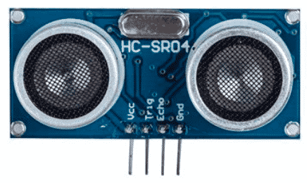
To complete this project, you will built on the circuit from Project 2. If you have completed Project 2, you will only need one additional component: the HCSR04 ultrasonic distance sensor. This sensor will replace the potentiometer.

The HC-SR04 ultrasonic distance sensor.
To save you from jumping to the Project 2 page, I'm copying the full list of components here.
The new item is #6:
- Two 5V DC motors.
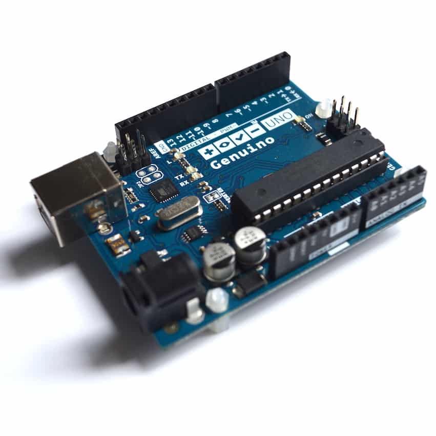
- An Arduino Uno.
- A motor controller module with the L298N chip.
- One AA-battery pack with 4 batteries.
- A bunch of jumper wires.
- A HCSR04 ultrasonic distance sensor.
The project 3 circuit
The new connections that relate to the ultrasonic distance sensor are #10, #11, #12 and #13.
Start by unplugging the Arduino from your computer so that it is not in operation.
- Connect the first motor to motor controller module Out1 and Out2. The order does not matter.
- Connect the first motor to motor controller module Out3 and Out4. The order does not matter.
- Connect the positive wire from the battery pack to pin +12V on the module.
- Connect the negative wire from the battery pack to pin GND on the module.
- Connect the GND pin of the module to the GND pin of the Arduino.
- Connect Arduino pin 5 to module pin In1.
- Connect Arduino pin 4 to module pin In2.
- Connect Arduino pin 3 to module pin In3.
- Connect Arduino pin 2 to module pin In4.
- Connect the sensor pin Vcc to Arduino pin 5V.
- Connect the sensor pin GND to Arduino pin GND.
- Connect the sensor pin Trig to Arduino pin 13.
- Connect the sensor pin Echo to Arduino pin 12.
- Inspect the wiring and ensure they are correct.
Here’s the schematic:

As with Project 2, the 9V batteries depict the motor battery power supply. The black module in the middle of the breadboard depicts the L298N motor driver module with the connections as described earlier.
The ultrasonic distance sensor uses 4 wires, two for power (5V and GND), one for the Trigger pin, and one for Echo. Connect those wires as per the instructions
Sketch for Project 3
Here's the sketch for this project.
//Arduino PWM Speed Control:
int E1 = 5;
int M1 = 4;
int E2 = 6;
int M2 = 7;
#define trigPin 13
#define echoPin 12
void setup()
{
Serial.begin (9600);
pinMode(M1, OUTPUT);
pinMode(M2, OUTPUT);
pinMode(trigPin, OUTPUT);
pinMode(echoPin, INPUT);
}
void loop()
{
long duration, distance;
digitalWrite(trigPin, LOW);
delayMicroseconds(2);
digitalWrite(trigPin, HIGH);
delayMicroseconds(10);
digitalWrite(trigPin, LOW);
duration = pulseIn(echoPin, HIGH);
distance = (duration/2) / 29.1;
move_motors(distance);
}
void move_motors(int distance)
{
if (distance >= 50 ){
Serial.print(distance);
Serial.println(" cm - 255");
digitalWrite(M1,HIGH);
digitalWrite(M2, HIGH);
analogWrite(E1, 0); //PWM Speed Control
analogWrite(E2, 0);
delay(30);
}
else {
int mappedVal = map(distance,0,50,0,255);
Serial.print(distance);
Serial.print(" cm - ");
Serial.println(mappedVal);
digitalWrite(M1,HIGH);
digitalWrite(M2, HIGH);
analogWrite(E1, 255-mappedVal); //PWM Speed Control
analogWrite(E2, 255-mappedVal); //PWM Speed Control
delay(30);
}
}
Much of this code, at least the part in the loop() function, has been taken from the sketch in Lecture 11. It generates the ping pulse that is emitted by the sensor, and then calculates the distance of an object from the time it takes for the echo to return.
Once the distance is calculated, the move_motors function is called, and the distance is passed as an integer parameter. Just like in Demo 2 Version 2, motors are moved in one of two ways: if distance is 50cm or less, the motor speed is proportional to the distance. The smaller the distance is, the smaller the speed. Otherwise, if the distance is over 50cm, then motors will move at their maximum speed.
If these motors were part of a fully assembled vehicle, the effect of this sketch would be that the vehicle would be capable of avoiding hitting an object by slowing down on approach, until it came to a full stop.
Upload the sketch and play with it to get a sense of it in “real life”. Try to imagine how it would behave in a real situation. Can you foresee any limitations? Can you imagine any improvements?
Improvements
For example, in the current version of the sketch, the vehicle would come to a complete stop only when the distance to a wall was 0cm. Is this sufficient? Perhaps it should come to complete stop a bit earlier, maybe at 5cm? Or perhaps, to be even more cautious, the vehicle should backup slightly away from the obstacle in order to provide room for a turns?
Can you make changes to the Demo 3 sketch and implement these scenarios (or whatever other improvement you can think of)?
Learn more
If you would like to learn how to use DC motors with your Arduino, consider enrolling to Arduino Step by Step Getting Serious.
We have a full section (Section 16) with 10 lectures dedicated to this topic.
New to the Arduino?
Arduino Step by Step Getting Started is our most popular course for beginners.
This course is packed with high-quality video, mini-projects, and everything you need to learn Arduino from the ground up. We'll help you get started and at every step with top-notch instruction and our super-helpful course discussion space.
Jump to another article
2. How to drive a DC motor without a motor driver module
3. What is "microstepping"?
4. Direct current motor
5. Project 1: Control two DC motors with your Arduino and the L298N controller
6. Project 2: Control speed and direction with a potentiometer
7. Project 3: DC motor control with a distance sensor
8. Project 1: Control a servo motor with a potentiometer
9. Project 2: Servo motor control with VarSpeedServo

Done with the basics? Looking for more advanced topics?
Arduino Step by Step Getting Serious is our comprehensive Arduino course for people ready to go to the next level.
Learn about Wi-Fi, BLE and radio, motors (servo, DC and stepper motors with various controllers), LCD, OLED and TFT screens with buttons and touch interfaces, control large loads like relays and lights, and much much MUCH more.
Last Updated 1 year ago.
We publish fresh content each week. Read how-to's on Arduino, ESP32, KiCad, Node-RED, drones and more. Listen to interviews. Learn about new tech with our comprehensive reviews. Get discount offers for our courses and books. Interact with our community. One email per week, no spam; unsubscribe at any time

