Introduction to the ESP32 guide series
Install the drivers CP2102 for the USB bridge chip
In this lesson, I will show you how to install the driver for the CP210x family of USB to UART bridge chips. This chip is used on many ESP32 development boards to support USB communications.
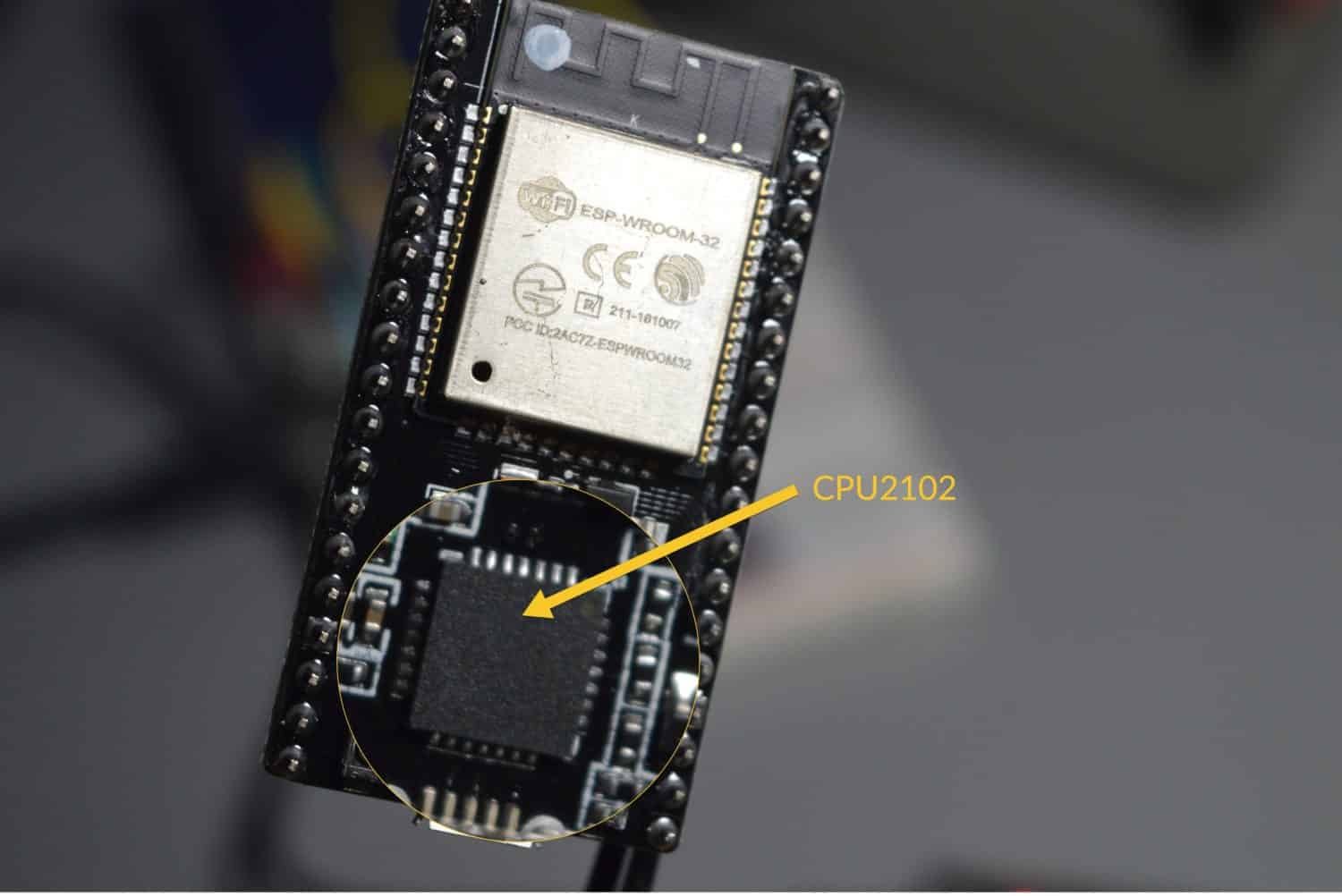
In this lesson, I will show you how to install the driver for the CP210x family of USB to UART bridge chips. This chip is used on many ESP32 development boards to support USB communications.
You can watch the video, or if you are the “reading” type, you can read the text below.
What is the CP210x USB to UART bridge?
Before we start experimenting with the ESP32 dev kit, I wanted to mention one issue that a lot of people come across, and that has to do with the sheer number of different development kits for the ESP32, and the small differences between them.
One of those differences has to do with the chip that is used to implement the USB to UART bridge which enables the USB programmability of the board.
My dev kit contains this chip, so I have to install the driver for the operating system, and it isn’t normally installed by default. So this chip here on my board, which is just stock standard as I’ve said before, requires a driver that typically is not installed by default on Windows or Mac OS computers and therefore has to be installed manually.
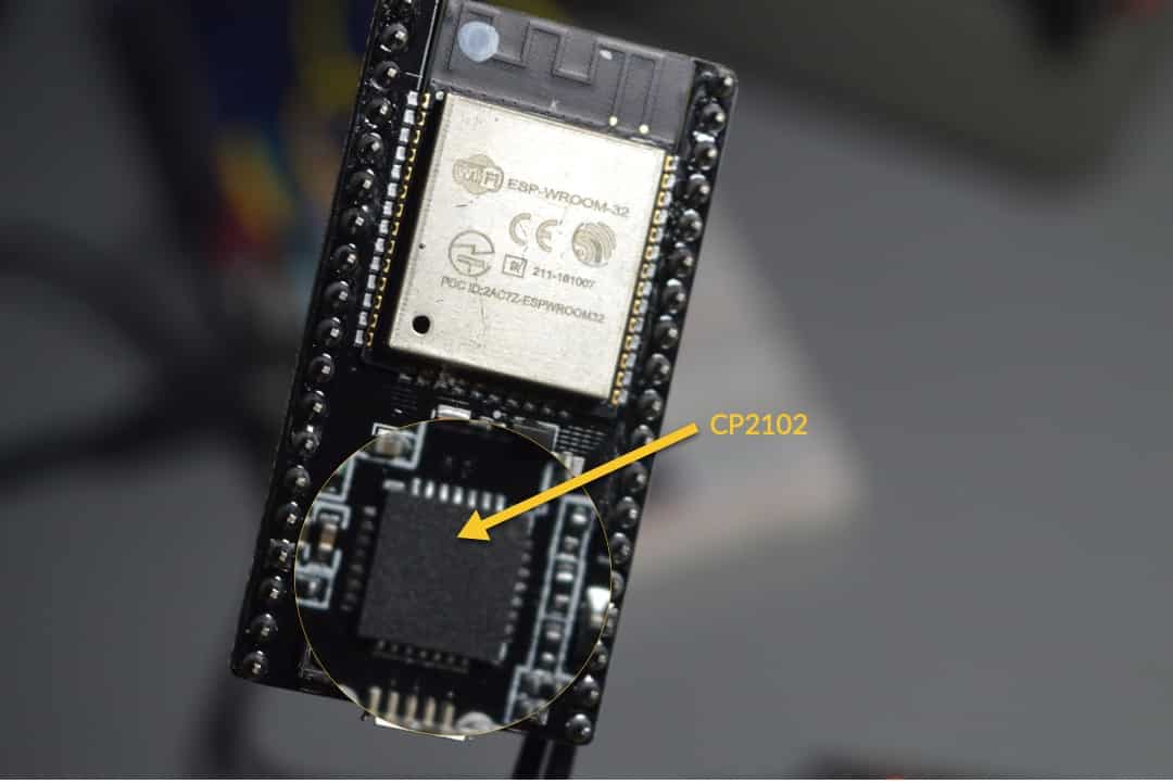
The CP2102 USB-UART bridge chip on my ESP32 dev board
Without installing this particular driver, you will not be able to upload a sketch to the board.
How to identify your board’s bridge chip
My particular board uses the CP2102 bridge chip. There’s a good chance that your board uses the same one or at least a bridge from the same CP210x family as these are all popular low-cost USB to UART bridge chips.
To identify the USB to UART bridge chip on your board, first try to read the model number from the package of the chip itself. If at all possible, you will need a strong magnifying glass. In most of my boards, the UART bridge chips have no readable text on them, so I had to investigate further.
Go to esp32.net/usb-uart/, where you will find lists of bridge chips and the dev board on which they are used.
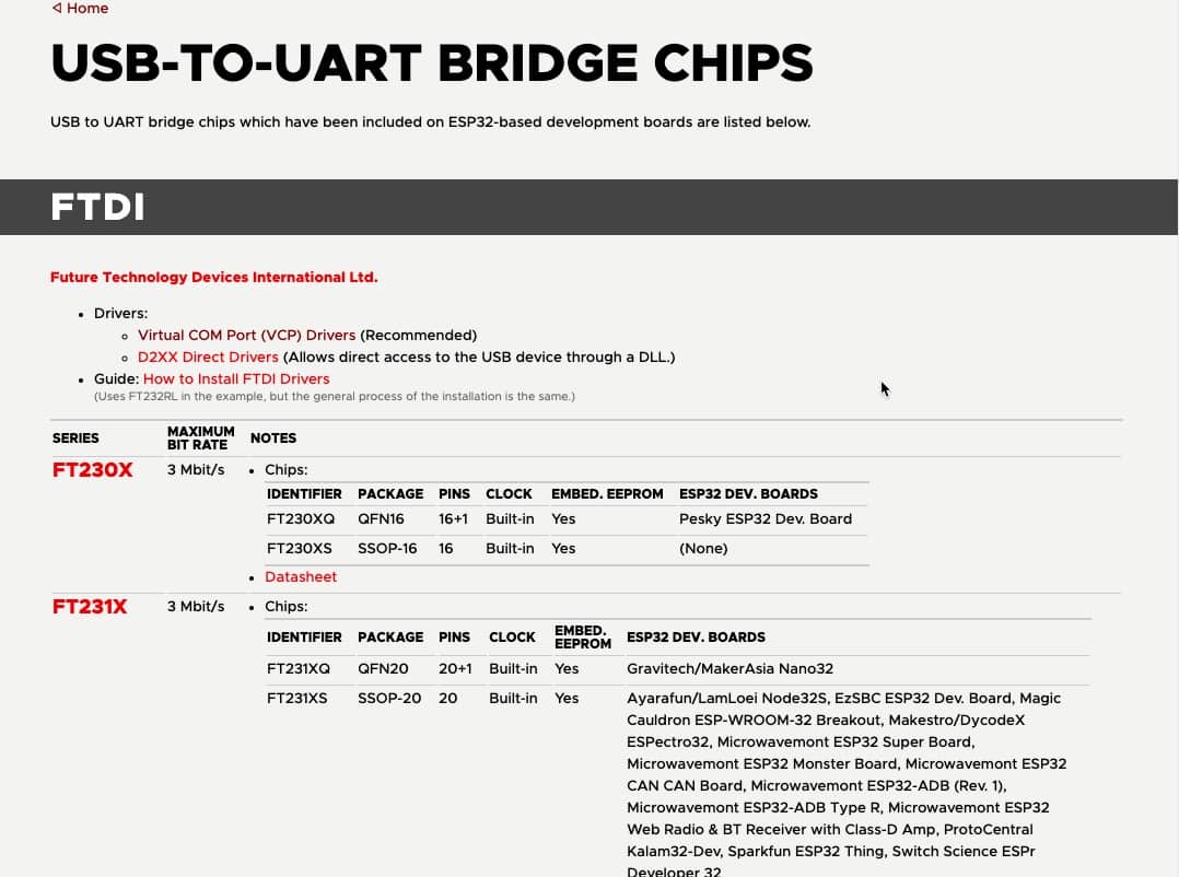
At esp32.net/usb-uart/, you will find information that will help you identify your board’s UART bridge chip.
How do you know if you need to install the bridge driver?
You might be one of the lucky ones. Your ESP32 dev kit may be using a USB bridge chip, which is already supported by your operating system.
To determine that, connect your development kit to your computer via USB.
Then, start up your Arduino IDE, and look under Tools, Port.
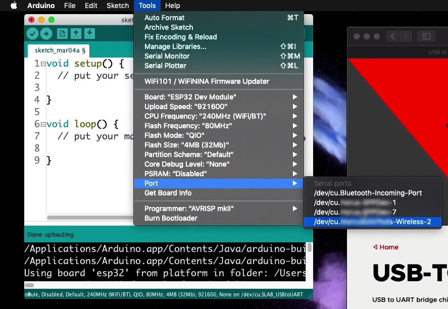
If your dev kit is connected to your computer, but its port is not listed under “Port,” you will need to install the USB-UART driver.
Can you see your dev kit port listed there? If not, you will need to install the third-party driver, so continue reading.
Install the USB-UART driver
Using the information available at esp32.net, determine the USB-UART bridge chip that is used in your ESP32 dev kit. I discovered that mine uses CP2102.
Once you have the model number, you need to find the driver that is appropriate for your operating system.
To do this, go to the Silicon Labs website. This link will take you directly to the driver download page.
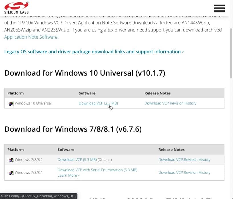
The source of the USB-UART bridge drivers for the CP210x chips is Silicon Labs.
This driver is available for a variety of operating systems. Download the one for your operating system and install it.
Most likely, you will need to restart your operating system. If you are not prompted to restart your operating system, be sure to restart the Arduino IDE.
Because of how many different drivers are out there and the differences between their operating systems and the exact installation procedure, I have not documented the driver installation process.
Verify the driver installation
After the driver installation is complete, you should test it.
Start, or restart, your Arduino IDE.
Connect your ESP32 development kit to your computer.
Click on the Tools menu, then click on Port.
Can you see your development kit listed?
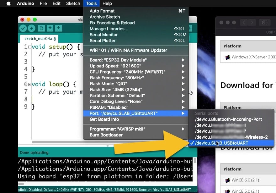
My dev kit is listed in the Port menu; the driver installation was successful.
Click on the dev kit port to make it the target for the Arduino IDE.
Let’s try and upload the current sketch. It’s ok that it is empty, we just want to verify that the Upload process works, nothing else.
Click on the Upload button (the IDE will probably ask you to save the sketch first; click Ok to that).
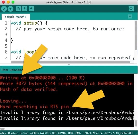
The test upload was successful.
Look at the log messages that appear in the Arduino IDE. You will be able to see the progress of the upload process until it reaches 100%, and the hash of the data is verified. Your board will then reset so that the newly uploaded sketch can start its execution.
And with this, your setup is complete, and you can start your experimentation with your ESP32. In the next lesson, you will learn how to make an LED blink, which is the obligatory first sketch for virtually any electronics platform.
🙂
Ready for some serious learning?
Enrol to
ESP32 for Busy People
This is our comprehensive ESP32 course for Arduino Makers.
It's packed with high-quality video, mini-projects, and everything you need to learn Arduino from the ground up.
Just click on the big red button to learn more.
Jump to another article
Lessons
1: The ESP32 module
2: The ESP32 Devkit
3: The ESP32 vs Arduino
4: The ESP32 GPIOs
5: The ESP32 communications
6: The ESP32 devkit power supply
7: Setting up ESP32 in the Arduino IDE on Mac OS
8: Setting up ESP32 in the Arduino IDE on Windows 10
9: Install the drivers CP2102 for the USB bridge chip
10: Digital output LED
11: Digital output PWM
Last Updated 1 year ago.
We publish fresh content each week. Read how-to's on Arduino, ESP32, KiCad, Node-RED, drones and more. Listen to interviews. Learn about new tech with our comprehensive reviews. Get discount offers for our courses and books. Interact with our community. One email per week, no spam; unsubscribe at any time
