Introduction to the ESP32 guide series
The ESP32 Development Kit
In this lesson, you will learn about the ESP32 “DevKit” or “developing kit.” At the time I am writing this, the latest development kit from Espressif is version four.

In this lesson, you will learn about the ESP32 “DevKit” or “developing kit.” At the time I am writing this, the latest development kit from Espressif is version four.
You can watch the video, or if you are the “reading” type, you can read the text below.
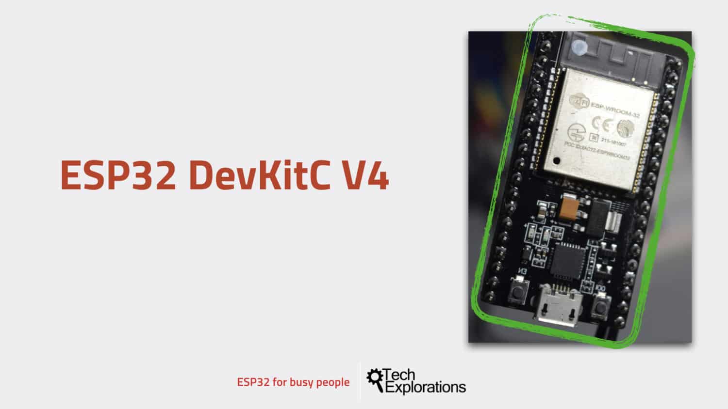
In the image here, you can see the ESP32 and the development kit on which the ESP32 module is situated.

The ESP32 DevKit version 4
The ESP32 dev kit exposes the ESP module's pins (at least some of those) to the outside world. Thanks to the dev kit, we can use the ESP32 by plugging it to a breadboard, or even attaching wires directly to its pins, without having to worry about implementing our own power, USB communications, reset circuit, etc.
Development kit core features and hardware
The core hardware that is present on the developing kit are things such as the USB-to-serial programming interface, the power subsystem that allows us to provide power within module push buttons for reset, and for setting it to the upload mode, indicator LCDs and a few other things.
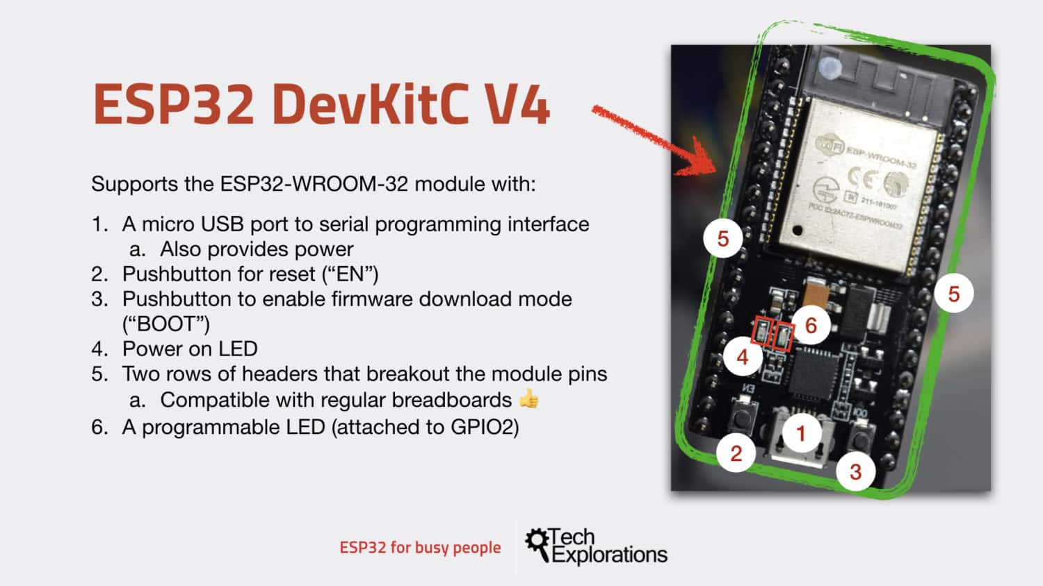
So in this image below, I've marked with numbers the most important features of the ESP32 dev kit.

The ESP32 DevKit v4 core features
You can see:
- The USB connector, which is also the way that we provide power to the ESB module and upload programs and also communicate with a serial monitor. It is a micro-USB port.
- The reset pushbutton. We use this button to reset the module and restart the execution of a sketch that is already uploaded.
- The “Enable” pushbutton. We use this button to place the module to upload mode. Variations of the development kit can place themselves into upload mode automatically, just like an Arduino can when connected to the Arduino IDE. The board I use in this guide does not, so I press button 3 immediately after I click on the “Upload” button in the Arduino IDE.
- The power-on LED. As long as your ESP32 is powered, that LCD will be on.
- The two rows of headers marked five here in this photo. These pins break out the pins from the ESP32 module so that they become compatible with the breadboard. This is another really nice aspect of the ESP32 development kit as opposed to the Arduino: The fact that the development kit is compatible with the breadboard.
- A programmable LED, which, in the case of my development board, is attached to GPIO 2. Be aware that not all development kits have this programmable LED. If yours doesn't have it, simply connect an external LED to GPIO 2, and you'll have the exact same functionality.
USB communication and power regulator
The square chip right above the USB connector is responsible for the UCB communications.
Above and to the right of the USB chip is another chip with four pins. This is the voltage regulator, which allows us to connect a voltage source from 5 to 12 V to the dev kit. You can learn more about the power options that you have with the ESP32 module in another lesson in this introductory series.
Other development kits
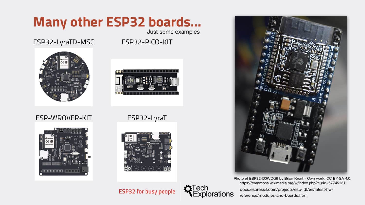
Before you move to the next lesson, I also wanted to mention that there is a variety of other development boards that host the ESP32 module.
For example, there is the ESP32 Lyra and the ESP32 Pico. Go ahead to learn more about them.

There is a variety of ESP32 Dev Kits.
A “naked” ESP32 module
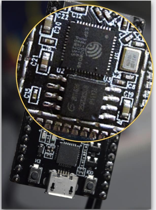
If you remove the cover, it reveals the bare module (don't remove the cover unless you are prepared to break your ESP32 module).
Zoom in, and you can see the two integrated circuits in it.

The ESP32 WROOM32 without its cover
Photo of ESP32-D0WDQ6 by Brian Krent - Own work, CC BY-SA 4.0, https://commons.wikimedia.org/w/index.php?curid=57745131
The larger one (this one here) is the ESP32 D0WDQ6 microcontroller, and the slightly smaller chip right here is the SPI flash memory.
So now you know what is beneath the cover. 🙂
Continue to the next lecture where you will learn about the differences and similarities between the ESP32 and the Arduino.
Ready for some serious learning?
Enrol to
ESP32 for Busy People
This is our comprehensive ESP32 course for Arduino Makers.
It's packed with high-quality video, mini-projects, and everything you need to learn Arduino from the ground up.
Just click on the big red button to learn more.
Jump to another article
Lessons
1: The ESP32 module
2: The ESP32 Devkit
3: The ESP32 vs Arduino
4: The ESP32 GPIOs
5: The ESP32 communications
6: The ESP32 devkit power supply
7: Setting up ESP32 in the Arduino IDE on Mac OS
8: Setting up ESP32 in the Arduino IDE on Windows 10
9: Install the drivers CP2102 for the USB bridge chip
10: Digital output LED
11: Digital output PWM
Last Updated 2 years ago.
We publish fresh content each week. Read how-to's on Arduino, ESP32, KiCad, Node-RED, drones and more. Listen to interviews. Learn about new tech with our comprehensive reviews. Get discount offers for our courses and books. Interact with our community. One email per week, no spam; unsubscribe at any time
