Introduction to the ESP32 guide series
ESP32 dev kit power options
In this lesson, you will learn how to power your ESP32 dev kit.
In this lesson, you will learn how to power your ESP32 dev kit.
You can watch the video, or if you are the “reading” type, you can read the text below.
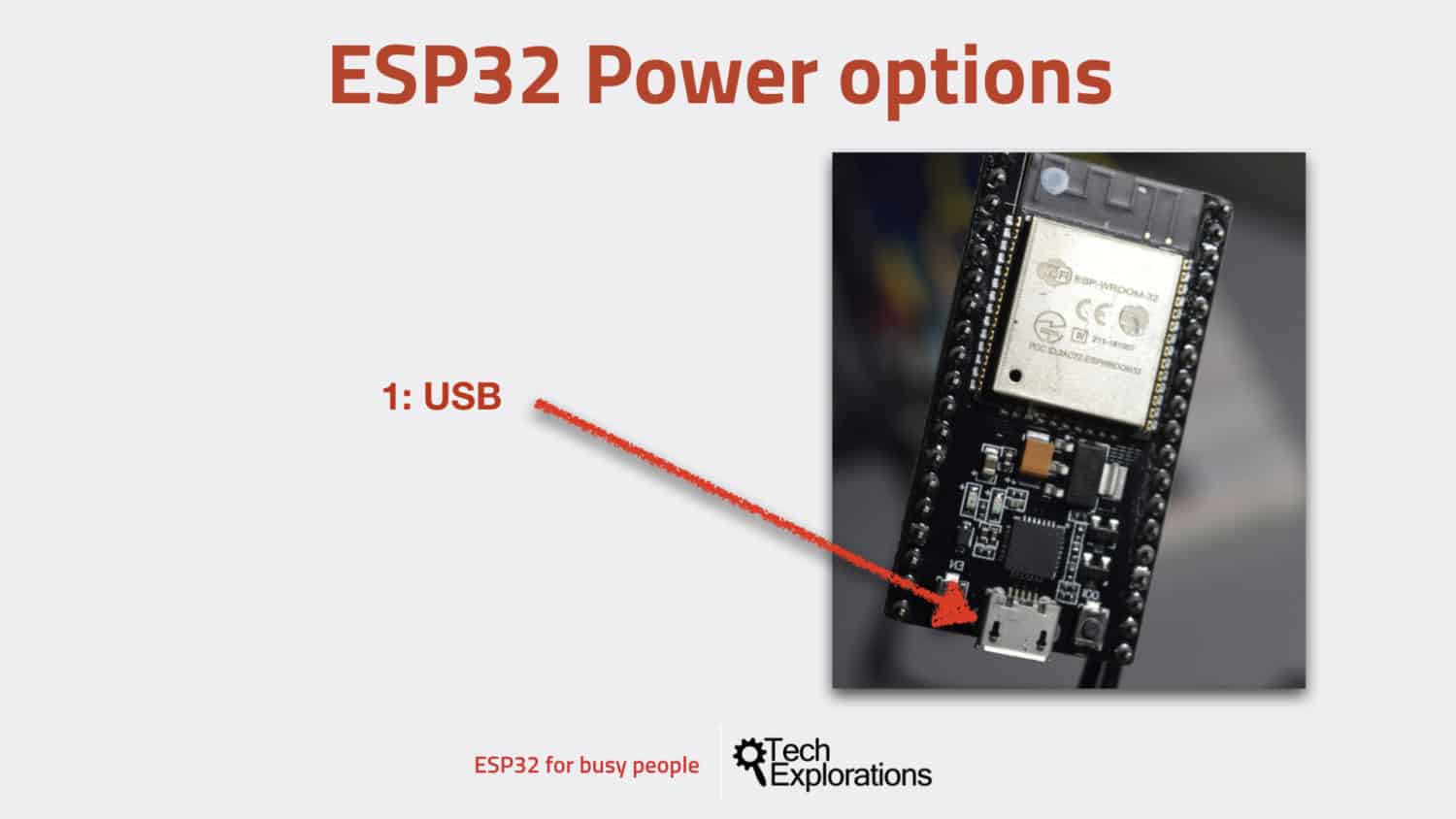
Option 1: USB
The easiest way to power your ESP32 dev kit is to use the USB port. The dev kit includes a micro USB port through which you can both supply power to the board, and implement serial communication with the host computer for uploading a sketch.

The easiest way to power your ESP32 dev kit is via the USB port.
Just plug one end of the cable into your computer’s USB port or to a USB compatible power, the other end to the USB port of the ESP32 dev kit, and you’re good to go.
Option 2: Unregulated power to GND and 5V pins
The second option is to connect an external unregulated power supply to the 5V pin and ground pins. Anything between around 5 and 12 Volts should work.
But it is best to keep the input voltage to around 6 or 7 Volts to avoid losing too much power as heat on the voltage regulator.
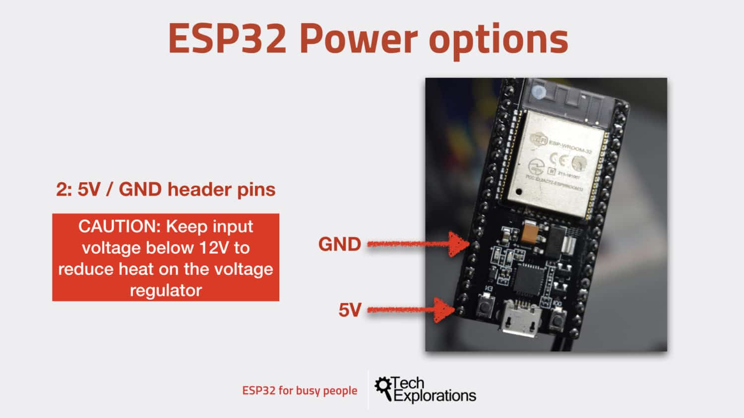
You can connect external power via the 5V and GND pins. Beware of the voltage limits.
I did some experimentation using my bench power supply. I supplied voltage between 5V and 10V and observed the current draw. The ESP32 was running a sketch with an empty loop.
At 10V input voltage, the current draw was 0.099 A (or 99.9mA).
At 5V, the current draw was a little higher, at 0.128 A (or 128mA).
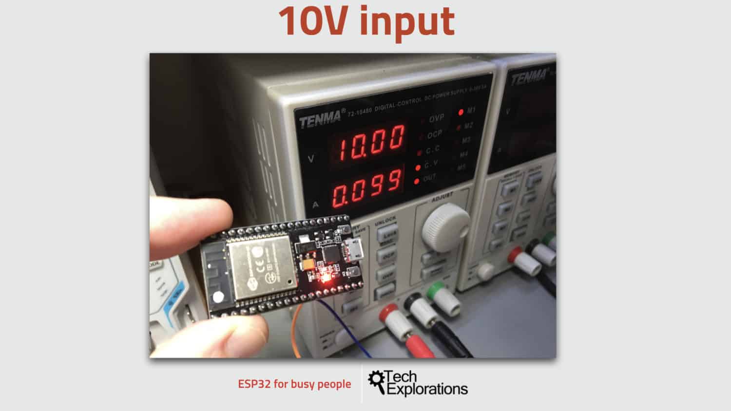
At 10V input voltage, the current draw was 99.9mA.
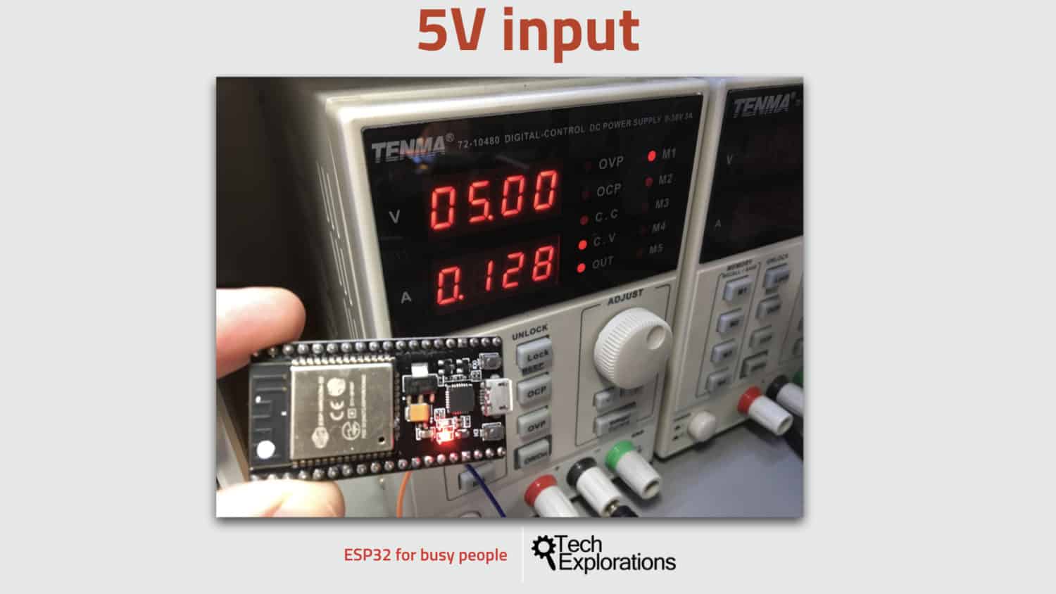
At 5V, the current draw was 128mA.
Option 3: Regulated power to GND and 3.3V pins
Another option that you have is to power your ESP32 is to use a 3.3V regulated power supply. For this, you will use the 3.3 Volt and GND pins.
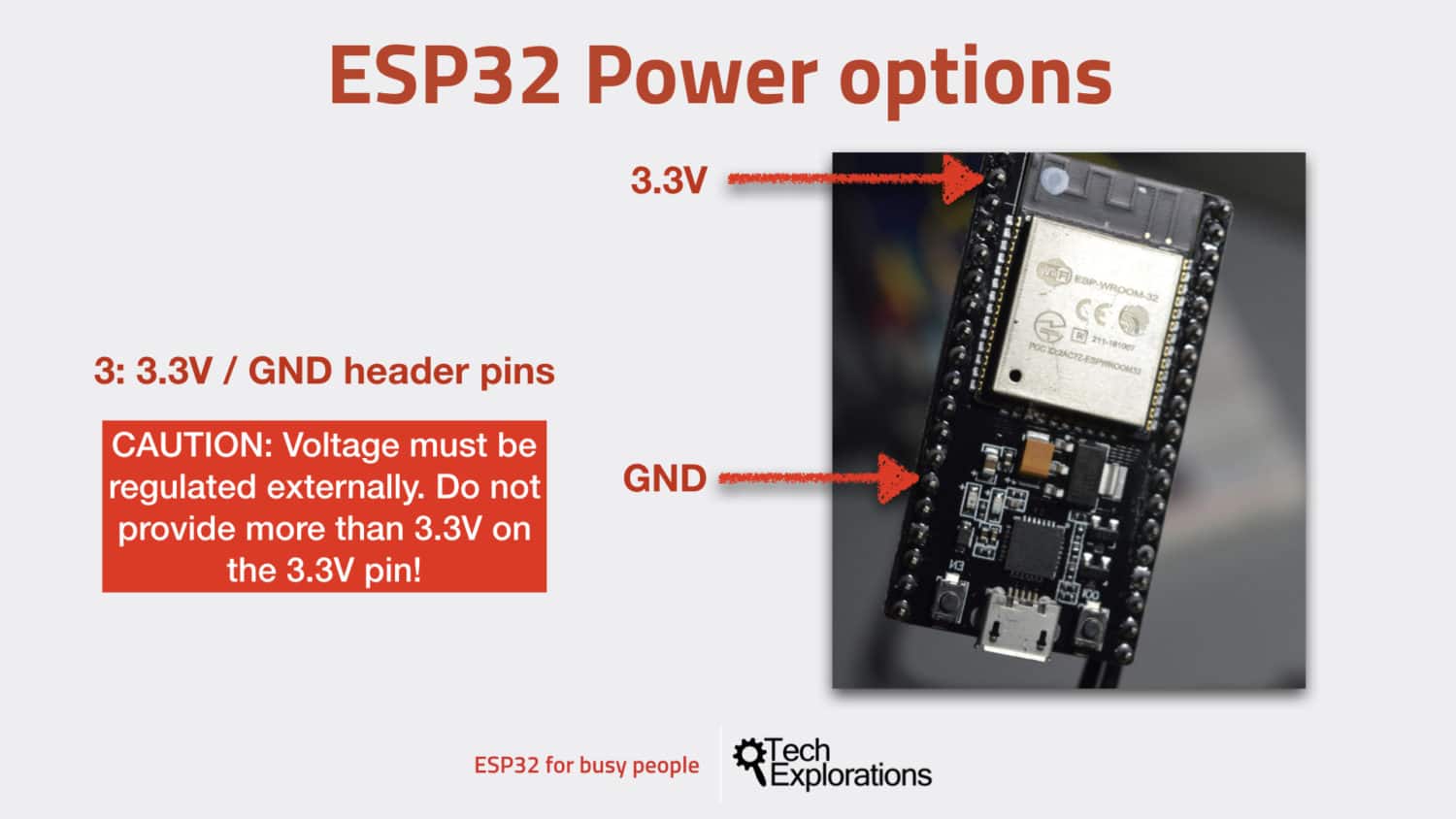
You can connect a regulated 3.3V voltage supply to the 3.3V and GND pins.
The 3.3 volts pin is at the top left of the board right next to the antenna.
You have to be very careful when you do that. If you power your ESP32 this way, you’re bypassing the on-board voltage regulator that is on board the dev kit, and therefore your module has no protection against over-voltage.
Again: Be very careful to make sure that your input voltage on the 3.3V pin is regulated and safe.
Power: conclusion
To power your ESP32 dev kit, you have three options:
- Via the USB port.
- Using unregulated voltage between 5V and 12V, connected to the 5V and GND pins. This voltage is regulated on-board.
- Using regulated 3.3V voltage, connected to the 3.3V and GND pins. Be very careful with that: do not exceed the 3.3V limit, or your ESP32 module will be damaged.
Attention: be very, very careful to only use one of those options at the same time.
For example, do not power your ESP32 dev kit via the 5V pin using a 10V input while at the same time you have the module connected to your computer via USB. This will surely damage your module, and perhaps even your computer.
With this, you should have a good understanding of what the ESP32 is, and you must be eager to get hands-on with it. I totally understand :-). Let’s proceed with the next lesson, where I’ll show you how to set up the ESP32-Arduino Core on the Arduino IDE.
Ready for some serious learning?
Enrol to
ESP32 for Busy People
This is our comprehensive ESP32 course for Arduino Makers.
It's packed with high-quality video, mini-projects, and everything you need to learn Arduino from the ground up.
Just click on the big red button to learn more.
Jump to another article
Lessons
1: The ESP32 module
2: The ESP32 Devkit
3: The ESP32 vs Arduino
4: The ESP32 GPIOs
5: The ESP32 communications
6: The ESP32 devkit power supply
7: Setting up ESP32 in the Arduino IDE on Mac OS
8: Setting up ESP32 in the Arduino IDE on Windows 10
9: Install the drivers CP2102 for the USB bridge chip
10: Digital output LED
11: Digital output PWM
Last Updated 1 year ago.
We publish fresh content each week. Read how-to's on Arduino, ESP32, KiCad, Node-RED, drones and more. Listen to interviews. Learn about new tech with our comprehensive reviews. Get discount offers for our courses and books. Interact with our community. One email per week, no spam; unsubscribe at any time
