Circuits guide series
Why should you use a diode in a relay driver circuit?
A relay is commonly used to drive large electrical loads. With a relay, your Arduino can control large motors, LED strips, lights, etc. But without a simple diode, your circuit can be easily damaged.
You can easily make a relay driver circuit with a transistor, a current limiting resistor (to turn the transistor on and off), and a diode in parallel with the relay coil.
The diode is often the cause of confusion: why do we need one?
I will explain...
Inductors
The coil of a relay device is that it is an inductor. An inductor will react to sudden changes in current by producing a large voltage across its ends.
To energize the relay, you must turn on the transistor so that current will flow between its emitter and collector. To de-energise the relay, you must turn the transistor off, which will interrupt the current flow between the emitter and collector.
This sudden change in the current that flows through the coil of the relay, will cause the coil to react. The result of this reaction is a large voltage across its leads.
Back-current suppression diode experiment
The diode is there to suppress this voltage so that it cannot damage any components around the relay, such as the transistor and the external battery supply (but also the controlling logic circuit, such as the Arduino).
To understand what is going on, I did a quick experiment on my oscilloscope.
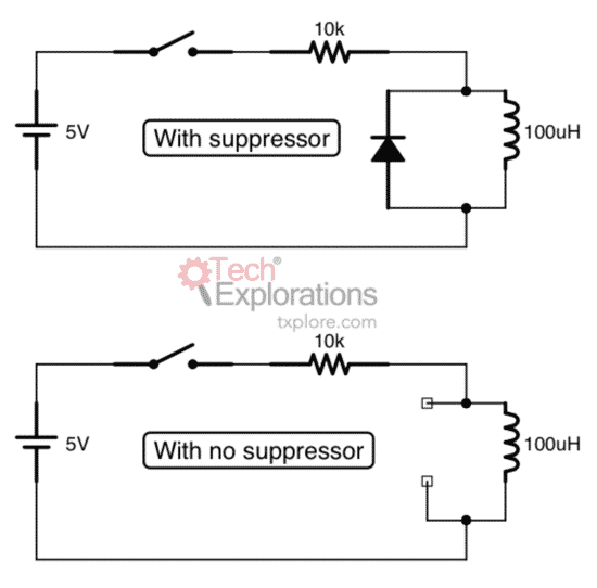
I used two versions of a simple circuit with a coil, button, power supply and current limiting resistor (pictured below).
In the first version, I use a diode as a suppressor for the voltage spike in the coil.
In the second version, I did not use the diode.
Here are the two circuits:
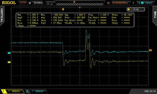
I used a channel (blue) on my scope for the trigger, and the other (yellow) to capture the voltage around the coil. The Yellow line is the coil voltage, and the Blue is the voltage on the switch (the trigger). You can ignore the blue line in the screenshots below.
Here is what the capture looks like without the diode:

The capture with the diode:
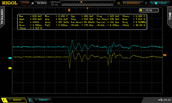
Look at the voltages, especially the Vpp one (Vpp: Voltage Peak-to-Peak).
Which one is larger? The one with, or without the diode?
If you look at the ending part of the waveform for the yellow line, for both circuits the voltage will eventually stabilize at the same value. Therefore the longer term (after around 350ns) effect of the diode is negligible (if any).
But just after the moment I press the button and energize the relay coil, the first line (no diode) shows a much bigger (in this case, roughly double) peak-to-peak voltage compared to the second line (with diode).
As you can see, the addition of the diode in a circuit that contains any kind of coil (like in a relay or DC motor) will significantly dumpen back currents by limiting the effect of the voltage accross the ends of the coil.
The Tech Explorations Subscription program
Subscribe and access all of our video courses immediately.
With a catalog of 25+ premium video courses (and growing), this subscription gives you an amazing resource to boost your learning.
Jump to another article
1. Pull-up & pull-down resistors
2. What is a bypass/decoupling capacitor?
3. What is the purpose of the diodes in a keypad circuit?
4. Logic level shifting
5. Why should you use a diode in a relay driver circuit?
6. Why use a voltage divider with a photoresistor?
7. Optoisolator: a simple way to electrically separate parts of a circuit
8. Use MOSFETs to drive large(ish) loads
New to the Arduino?
Arduino Step by Step Getting Started is our most popular course for beginners.
This course is packed with high-quality video, mini-projects, and everything you need to learn Arduino from the ground up. We'll help you get started and at every step with top-notch instruction and our super-helpful course discussion space.
Done with the basics? Looking for more advanced topics?
Arduino Step by Step Getting Serious is our comprehensive Arduino course for people ready to go to the next level.
Learn about Wi-Fi, BLE and radio, motors (servo, DC and stepper motors with various controllers), LCD, OLED and TFT screens with buttons and touch interfaces, control large loads like relays and lights, and much much MUCH more.
Last Updated 1 year ago.
We publish fresh content each week. Read how-to's on Arduino, ESP32, KiCad, Node-RED, drones and more. Listen to interviews. Learn about new tech with our comprehensive reviews. Get discount offers for our courses and books. Interact with our community. One email per week, no spam; unsubscribe at any time

