Arduino programming guide series
Simple multitasking on the Arduino
Simple multitasking on the Arduino

The bulk of CPUs used in desktop or laptop computers ten or fifteen years ago where also mostly single-core, as opposed to modern multi-core systems. Despite this "handicap", they were able to execute multiple processes at, seemingly, the same time (concurrently). You could have your web browser rendering a web page while your email client was downloading a bunch of emails.
How was this possible?
And if it was possible to have multitasking on a single-core computer CPU ten years ago, why not have the same ability on a single-core microcontroller?
The key to multitasking is efficient and clever programming. Thanks to multitasking infrastructure integrated into modern operating systems, it was possible to divide CPU time into small chunks and allocate each chunk to a different process. The operating system was responsible for allocating these time chunks to the processes that needed them based on various scheduling algorithms. Even though the resources that a desktop CPU has been vastly superior to those that a microcontroller has, the key ingredient is the same: time.
The Arduino has no operating system.
Therefore, if we want to implement multitasking, we will have to create at least a basic infrastructure that supports it. We also have to create a sketch that also implements the functionalities we need.
In a desktop operating system, scheduling does exactly what the word says:
- Start Process A at time X and stop it after Yms.
- Start Process B at time X+5 and end it at time Zms.
And so on.
Let's say that Process A is turning a red LED on (connected to pin 9), and Process B is turning a green LED on (connected to pin 8).
Usually, if we want to turn an LED on for 100ms, then turn it off, we would do it like this?
digitalWrite(9,HIGH);
delay(100);
digitalWrite(9,LOW);
The LED will turn on, then 100ms later will turn off. The microcontroller will be locked for anything other than an external interrupt for 100ms.
If we needed to turn on the green LED 5ms after the red LED turned on, we would not be able to do it using delay() because the microcontroller is still counting milliseconds for the red LED.
We will have to wait until the red LED is turned off, a whole 95ms after then the actual time that we wanted the green LED to turn on:
digitalWrite(9,HIGH);
delay(100);
digitalWrite(9,LOW);
digitalWrite(8,HIGH);
delay(100);
digitalWrite(8,LOW);
This is an example of how using delay() forces us to implement strictly single-processing systems, and how it forbids certain functionalities, like turning the green LED on while the microcontroller is locked in the delay() function.
In a separate article, I explained how to use a common technique that can help us to avoid the use of the delay() function. By avoiding the delay function, we can utilze the otherwise wasted compute cycles and get closer to a multi-tasking environment on an Arduino board.
Here, I would like to expand on what I wrote about delay() in that article and give an example of how you can use the technique I described there to implement basic multitasking.
In the example that follows, I use this technique to show you how to create a sketch that blinks two LEDs, red and green, according to my desired schedule. For example, turn the red LED on at time X, green LED on at time X+5, red LED off at time X+100, and green LED off at time X+103.
Notice: the actual timings in the sketch may be different, as I have been playing around with it.
Total ON time for LEDA is 100ms, and for LEDB is 98ms.
Let's also make the total OFF LEDA time 200ms and for LEDB 250ms.
You can copy the sketch from the Gist on Github.
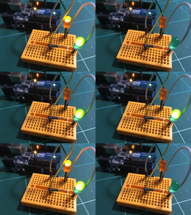
Run this sketch on an Arduino with two LED connected, and you will see something like this:

In this example sketch, for each LED (or time-dependent function that we want to implement), we use four variables to create a schedule:
- The total elapsed time for the ON LED state
- The total elapsed time for the OFF LED state
- The last time we made a change to the state of the led.
- The offset.
The pattern is this: if the time we want the LED to be in a specific state has elapsed, move it to the other state. The offset value is used to "push" the ON/OFF cycle forward in time; this is useful if you wish to schedule more than one activities to start at different times.
The result of this time of programming method is known as a "state machine." A state machine is a program or a machine which can be only in one of several states at any given time. The specific state in which the machine will be depend on rules, which in turn rely solely on past and present conditions. There are state machines that have states that are deterministic, or non-deterministic.
For example, in our sketch, a rule determines that if 5ms have elapsed and LEDA if OFF, then LEDA should become ON.
The state of this LED will not change unless another rule is triggered in the future which will take into account the state of the LED and of other variables that describe its environment (in our case, just the millis and the last time that the state of LEDA was changed) to decide if LEDA should be turned OFF.
Using the state machine paradigm, you can implement the efficiency of multitasking on your Arduino.
Indeed, this kind of manual multitasking is not as easy as multitasking is on the desktop. The absence of an operating system means that you, the programmer, have to design the scheduling rules and then implement them in code.
For a small number of states, this is a manageable problem.
What if you have more complicated requirements? Good news: There are ways to abstract multitasking on microcontrollers using libraries! But, this is something for another article in this series.
New to the Arduino?
Arduino Step by Step Getting Started is our most popular course for beginners.
This course is packed with high-quality video, mini-projects, and everything you need to learn Arduino from the ground up. We'll help you get started and at every step with top-notch instruction and our super-helpful course discussion space.
Jump to another article
3. Focus on the type parameter in "println()"
4. "0" or "A0" when used with analogRead()?
5. What is the "_t" in "uint8_t"?
6. Save SRAM with the F() macro
7. What is the gibberish in the Telnet output?
9. Confusing keywords? follow the source code trail
10. The interrupt service routine and volatile variables
11. The problem with delay() and how to fix it
12. How to deal with the millis rollover
13. Can you use delay() inside Interrupt Service Routine?
15. A closer look at line feeds and carriage returns
16. Understanding references and pointers
17. Simple multitasking on the Arduino
19. Concurrency with the Scheduler library on the Arduino Due and Zero
20. Bitshift and bitwise OR operators
21. What is a "static" variable and how to use it
22. Understanding the volatile modifier

Done with the basics? Looking for more advanced topics?
Arduino Step by Step Getting Serious is our comprehensive Arduino course for people ready to go to the next level.
Learn about Wi-Fi, BLE and radio, motors (servo, DC and stepper motors with various controllers), LCD, OLED and TFT screens with buttons and touch interfaces, control large loads like relays and lights, and much much MUCH more.
Last Updated 2 years ago.
We publish fresh content each week. Read how-to's on Arduino, ESP32, KiCad, Node-RED, drones and more. Listen to interviews. Learn about new tech with our comprehensive reviews. Get discount offers for our courses and books. Interact with our community. One email per week, no spam; unsubscribe at any time

