Arduino Sensors & Actuators guide series
How to use a potentiometer
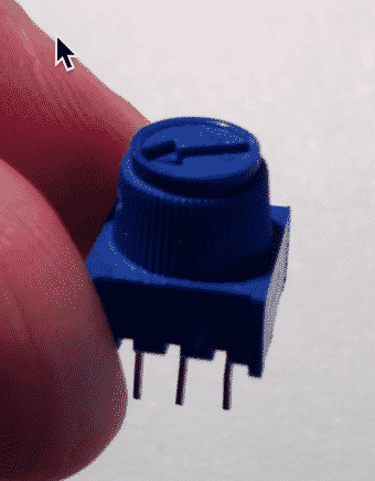
A potentiometer is a device that allows you to change the value of a resistance by turning a knob. In this tutorial you will learn how to use a potentiometer.

A potentiometer is a device that allows you to change the value of a resistance by turning a knob.
In this tutorial you will learn how to use a potentiometer.

A potentiometer is a very simple sensor. It senses the position of its knob.
Let's put this circuit together, and then we'll discuss how it works. In particular, we'll see what is happening inside the potentiometer.
Simulation
I have recorded a short video to show you how to run this experiment inside a simulator. This is the best way to experiment with the Arduino if you don't have the real thing. Be sure to read the complete tutorial to understand the details of the circuit and the sketch.
But if you are in a hurry, watch this video.
Circuit assembly
Let's assemble the circuit. You will need:
- The Arduino
- A potentiometer
- An LED
- A resistor to protect the LED (I used a 1kΩ resistor, but you can use any value from 220Ω to 1kΩ)
As you turn the knob of the potentiometer, the resistance connected to its output pin changes. This in turn changes the voltage on that pin. This output voltage is read by the Arduino at analog pin 0 (A0).
The Arduino will then use digital pin 11 to drive the LED. Although pin 11 is digital, we are using its Pulse Width Modulation (PWD) feature, like we did back in Lecture 5. We just glossed over this feature back then: we used the analogWrite instruction which makes use of this feature. Later in this lecture I will explain how PWD works.
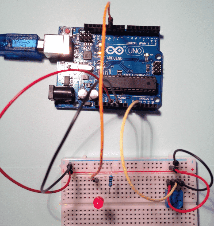
This circuit uses a potentiometer to control the brightness of an LED.
Here’s a photo of the assembled circuit on my breadboard:

The experiment circuit on my breadboard.
Potentiometer, principle of operation
The potentiometer contains a voltage divider. A voltage divider is a simple arrangement of two resistors that can reduce an input voltage to a smaller voltage that depends on the resistors that make up the circuit.
In a potentiometer, we still have these two resistors inside the package, but at least one of them is variable,. This means the resistance of the resistor inside the potentiometer changes as we turn the knob.
In the diagram on the right, the pin in the middle is connected to a dial that is made of conductive material, like copper. They gray-coloured circle represents a resistor, with its two ends connected to V+ and Ground. As the dial comes in contact with different parts of the resistor, it samples a voltage between V+ and ground, and we can read this voltage from the middle pin.
So there you have it, a potentiometer is nothing more than a variable voltage divider.

A variable resistor, like the one inside a potentiometer.
Want to learn electronics?

Our course "Basic Electronics for Arduino Makers" is designed specifically for people that use the Arduino as a learning and creativity tool.
This course will teach you the basics of electronics so that you know what things like current limiting resistors, voltage dividers, power supplies, transistor switches, Ohm's Law, and lots more, actually are.
What is Pulse Width Modulation?
You learned about Pulse Width Modulation in the tutorial on how to make an LED fade on and off. If you haven't completed that tutorial yet, please do that now because you will need that knowledge going forward. In fact, in this experiment you will use PWM to control an LED, just like you did in the fading LED tutorial. The difference is that in this tutorial, you will control the PWM value through the potentiometer. In the fading LED tutorial, the Arduino controlled the PWM value inside a loop in the sketch.
But since we are on the topic of PWM, let's have another look at it.
Arduino's digital pins can output HIGH and LOW, as we have already seen. Some of these digital pins, however, are special: although they can still only output HIGH and LOW, their output can be modulated is a way that this output can behave as if it was analog.
Have a look at the diagram below, taken from the Arduino web site.

PWM and duty cycles (original: arduino.cc)
A "normal" digital pin outputs 0V or 5V, like in the top and bottom waveform examples. But, in a pin that supports PWM, we can output 5V for only part of the period. In the second waveform, for example, we output 5V for 25% of the period, and 0V for the rest. In the third example, its 50% and 50% respectively.
On the LED, this kind of modulation on the output signal has an effect similar to using an analog pin and outputting voltage in the range of 0V to 5V. In effect, we simulate analog output using a digital pin!
The sketch
Here's the sketch that drives this circuit (here is the sketch on Github):
int potentiometerPin = 0;
int ledPin = 11;
int potentiometerVal = 0;

void setup()
{
  Serial.begin(9600); // setup serial
}

void loop()
{
  potentiometerVal = analogRead(potentiometerPin); //I use the map function because PWM pins can only accept
                                                   //values from 0 to 255. Analog pins can output values from
                                                   //0 to 1023. With the map function, the range 0-1023 is

                                                   //converted to appropriate values from 0 to 255.

  int mappedVal = map(potentiometerVal,0,1023,0,255);
  Serial.print(potentiometerVal);
  Serial.print(" - ");
  Serial.println(mappedVal);
  analogWrite(ledPin,mappedVal);
  delay(10);
}
There is nothing new here. We have seen the "map" function in an earlier lecture, so you know that this function is used when we want to make a range of values fit within another range of values. In this case, we read values in the range of 0 to 1023 from analog pin 0, and we want to make this fit in the range 0 to 255, which is what the pulse width modulation-capable pin 11 can output.
Other than that, we simply use the "analogRead" function to read a value from analog pin 0, and the "analogWrite" function to create a PWM pulse on digital pin 11.
Ready for some serious Arduino learning?
Start right now with Arduino Step by Step Getting Started
This is our most popular Arduino course, packed with high-quality video, mini-projects, and everything you need to learn Arduino from the ground up.
Jump to another article
1: Introduction
2: How to make an LED blink
3: How to make an LED fade
4: How to use a button
5: How to use a potentiometer
6: Infrared line sensor
7: Measuring light
8: Detect tilt and impact
9: Measuring acceleration
10: Detect motion with the ultrasonic sensor
11: Detect motion with PIR sensor
12: Temperature and barometric sensor BME280
13: Measuring Temperature And Humidity
Last Updated 1 year ago.
We publish fresh content each week. Read how-to's on Arduino, ESP32, KiCad, Node-RED, drones and more. Listen to interviews. Learn about new tech with our comprehensive reviews. Get discount offers for our courses and books. Interact with our community. One email per week, no spam; unsubscribe at any time