Arduino Sensors & Actuators guide series
How to make an LED blink on and off
A Light Emitting Diode (LED) is a special kind of a diode that can emit light.
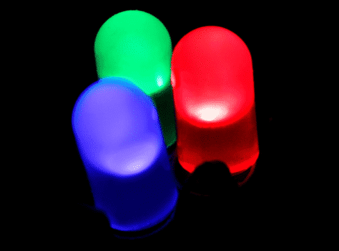
A Light Emitting Diode is a special kind of a diode in that it can emit light. Although all diodes do emit light, in most cases this light is not bright enough so we can't see it. LEDs are specially constructed to allow the light produced to escape outwards so we can see it instead of just being absorbed by the semiconductor.
A diode is a polarised device. In a polarised device, there is a correct way and an incorrect way of connecting it to your circuit. Connecting a polarised device to your circuit incorrectly will, at least, result in your device not working. In some cases the device can burn out.

LEDs come in several colours, including white. There are even LEDs that can generate thousands of colours by combining the three primary: red, green, blue.

This is what an LED device looks like. Notice that there is a short and a long "leg". The short leg is called "the cathode", often noted with a "k" and should be connected to the negative ("-") voltage. The longer leg is called "the anode", often noted with an "a" and should be connected to the positive ("+") voltage. Other devices of note that are polarised and use similar or same terminology are transistors and certain types of capacitors.
Symbolically, i.e. in diagrams depicting electronic circuits, an LED is depicted like this:
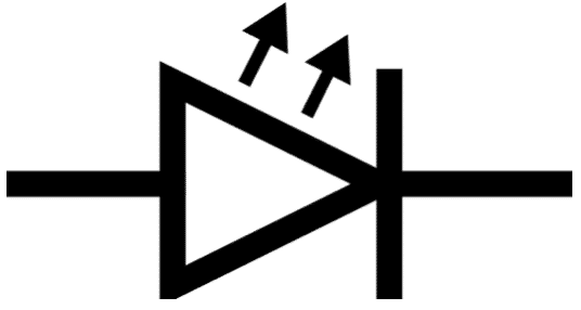
The schematic symbol for an LED
The basic characteristic of a diode is that it is a semiconducting device that allows the flow of electricity (electrons) only towards one direction. Think of it as the equivalent of a plumbing valve that allows water to flow only in one direction. Therefore, diodes are used in situations where we want to restrict the directionality of electricity. Diodes are used extensively in applications like the conversion of current from alternating to direct, in radio transmitters for the modulation of signals, and many others.
The symbol of a diode is almost the same as the one for an LED. The only difference is the presence of three little arrows which show that light is emitted from an LED:
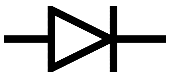
The schematic symbol for a regular LED
Simulation
I have recorded a short video to show you how to run this experiment inside a simulator. This is the best way to experiment with the Arduino if you don't have the real thing. Be sure to read the complete tutorial to understand the details of the circuit and the sketch.
But if you are in a hurry, watch this video.
Let's experiment with an LED
With the background and theory behind us, let's implement our first Arduino circuit. The aim is to become familiar with plugging components into the breadboard, uploading and running a sketch.
In our first sketch we will simply make an LED blink on and off.
Here's a diagram of the circuit you need to build now.
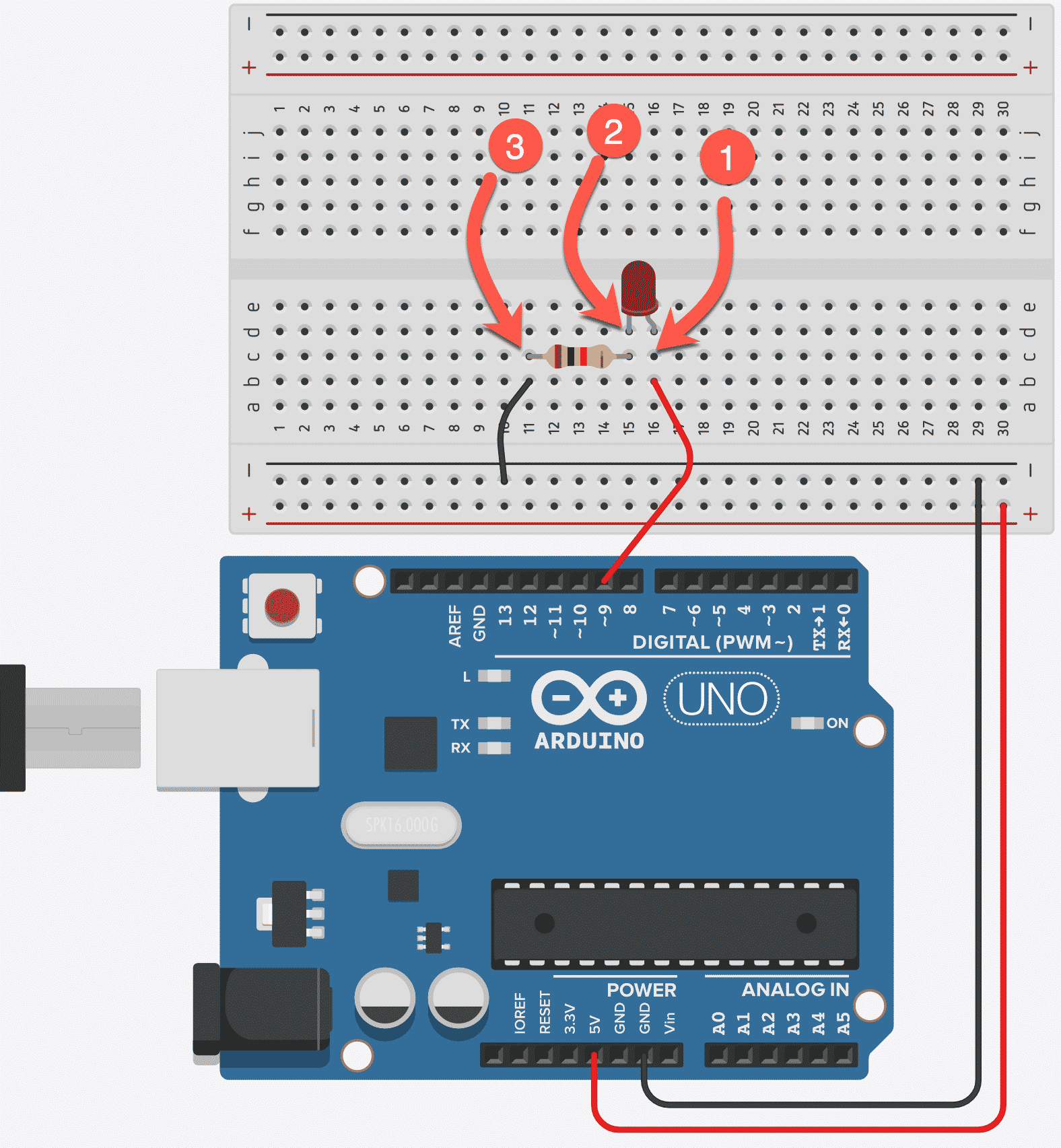
The wiring diagram for the "blinking LED" experiment.
Follow these steps to wire this circuit:
- Use a red jumper cable to connect the Arduino digital socket (pin) 9 to any socket in an empty column on the breadboard. Let's name this column "1".
- Take an LED, and notice that it has two pins, with one longer than the other. The longer pin is the anode, and the short pin is the cathode. We always connect the cathode towards the GND pin of the Arduino.
- Connect the anode of the LED in column 1 of the breadboard (the same column in which you connected the red jumper wire).
- Take a resistor (it can be any value between 220 Ohm and 500 Ohm, and this experiment will work well), and connect one pin in one of the sockets of column "2" in the breadboard. It doesn't matter which pin it is since the resistor, unlike the LED, can work the same either way you connect it. Connect the other pin of the resistor in a socket in an empty column (make this column "3").
Connecting a resistor in series with an LED is important. The LED has a very small resistance on its own. If you connect it to your Arduino without a resistor, it will result to a large current flowing through it. This can damage the LED, but worse, it can damage your Arduino.
This is described mathematically by Ohm's Law, which states that R=V/I, where R is the resistance of a device, V is the voltage at its two connectors, and I the current that flows through it. If you solve this equation for I, you get that I=V/R. For an LED, R is almost zero, so no matter what the V is, the I will be a very large number.
Want to learn electronics?
Our course "Basic Electronics for Arduino Makers" is designed specifically for people that use the Arduino as a learning and creativity tool.
This course will teach you the basics of electronics so that you know what things like current limiting resistors, voltage dividers, power supplies, transistor switches, Ohm's Law, and lots more, actually are.
The LED is a "POLARISED device". What does this mean?
In electronics, there are several devices, like an LED, that are "polarised". This means that you have to be careful how you connect them to a circuit.
Polarised devices have a positive and a negative pin. The positive pin is called "anode", and the negative is called "cathode".
Examples of polarised devices, apart from the LED, are electrolytic capacitors, batteries, diodes, and operational amplifiers.
In the circuit of this experiment, the tricky part has to do with connecting the LED in accordance with its polarity. The "rule of thumb" is to remember that the anode (the positive pin) is longer longer than the cathode (the negative pin), just like any positive number is bigger than any negative number. Always connect the cathode towards the GND pin of your Arduino.
To finish up with the wiring, plug the Arduino USB cable into an available USB port in your computer. What you should have now is something like this:
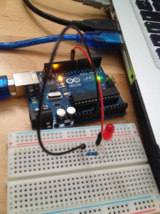
Connect your Arduino to your computer via the USB cable.
The program, a.k.a. "sketch"
The LED isn't doing anything at the moment. To get it to light up and blink, we need to upload a sketch to the Arduino with the appropriate instructions.
Here's the program we'll use. I'll explain how it works. You can either type it into a new Arduino IDE editor window, or load it by selecting File > Examples > 01. Basics > Blink from the Arduino IDE menu. If you do this, remember to change the number "13" to "9" for variable "led". I also made it available as a text file download from the materials tab.
// give a name to the pin to which the LED is connected:
int led = 9;

// the setup routine runs once when you press reset:
void setup() {
    // initialize the digital pin as an output.
    pinMode(led, OUTPUT);
}

// the loop routine runs over and over again forever:
void loop() {
    digitalWrite(led, HIGH); // turn the LED on
    delay(1000); // wait for a second
    digitalWrite(led, LOW); // turn the LED off
    delay(1000); // wait for a second
}
Because this is your first ever Arduino program, I will explain a few things before continuing:
Need a programming refresher?
Comments
Any text following "//" or in-between "/*" and "*/" is a comment, and the Arduino will ignore it.
People use these symbols to type comments, like in this example.
Functions
An Arduino program can be broken down in parts by using functions. Functions make it easy to create little programs within a large program, and to call each of these little programs by name.
In this example, we used two functions with names setup() and loop().
These are special functions that the Arduino will call itself. When the Arduino starts, it will first call the setup() method and execute any commands it finds inside. Then, it will call loop() again and again until you turn off the power, every time executing whatever commands it finds inside. You can create your own functions and name them whatever you like, as long as you don't use a reserved name (like "loop" or "setup").
Function names can't have white spaces or other "special" characters inside them.
A function may or may not return a value when it finishes its execution. Notice that loop is declared as void loop()? The void means that loop does not return anything when it finishes its execution. Same thing happens with setup().
Local and global variables
If you want to store and retrieve values in your sketch, you need to use variables. Variables can store numbers, text, booleans (true/false values) and other data types. In the very beginning of this example, we have this statement:
int led = 9;
This creates a global variable named led, and stores the value 9 in it, which is of type int (integer).
A global variable is accessible from anywhere in your sketch.
In this example, you can see that inside the setup() function, there is a reference to "led", and similarly there is a reference to "led" from inside the loop() function.
On the other hand, a local variable is one that is only accessible from within its own context.
If we had declared the led variable inside the setup() function, then it would only be accessible by other statements inside the setup() function and would not be accessible from the loop() function.
Arduino functions
Arduino's magic is in the functions that are build-in to the language. These functions make it easy to control many aspects of our hardware.
Notice that in the setup() function, there is a call to the function pinMode. This function takes in two parameters: first the number of the pin we want to configure, and second the mode that we want to assign to this pin.
In our example, we have pinMode(led, OUTPUT);. Remember that we have a global variable called led in which we stored the number "9". So we can re-write the pinMode instruction as pinMode(9, OUTPUT);.
This means that we configure pin 9, which is a digital pin with possible states HIGH (5V) and LOW (GND) to be an output. Being an output, this pin can be used to send a value to a connected device, in our case the LED.
With the setup() function complete, the Arduino then starts calling the loop() function. The first thing that happens there is calling the digitalWrite function:
digitalWrite(led, HIGH);
With digitalWrite, we assign a new state to a pin. We can rewrite this statement as digitalWrite(9, HIGH);, and, as you can probably guess, we are changing the state of pin 9 to HIGH, which is 5V. As soon as this happens, your LED will light up!
We want to keep this LED lit for a little while, so we use the instruction delay to keep things as they are. delay accepts one parameter, that is the number of milliseconds to wait for.
So in our case:
delay(1000);
means: "wait for 1000 milliseconds", which is 1 second.
Then we call digitalWrite again, but this time we change the state of pin 9 to LOW, which is 0 Volts.
digitalWrite(9, LOW);
We wait at this state for another second, then the loop starts all over again.
So there you have it, your first Arduino circuit, and a blinking LED!
In the next tutorial, we will make the same LED, using the exact same circuit, fade on and off, giving us a much nicer visual effect to look at.
Ready for some serious Arduino learning?
Start right now with Arduino Step by Step Getting Started
This is our most popular Arduino course, packed with high-quality video, mini-projects, and everything you need to learn Arduino from the ground up.
Jump to another article
1: Introduction
2: How to make an LED blink
3: How to make an LED fade
4: How to use a button
5: How to use a potentiometer
6: Infrared line sensor
7: Measuring light
8: Detect tilt and impact
9: Measuring acceleration
10: Detect motion with the ultrasonic sensor
11: Detect motion with PIR sensor
12: Temperature and barometric sensor BME280
13: Measuring Temperature And Humidity
We publish fresh content each week. Read how-to's on Arduino, ESP32, KiCad, Node-RED, drones and more. Listen to interviews. Learn about new tech with our comprehensive reviews. Get discount offers for our courses and books. Interact with our community. One email per week, no spam; unsubscribe at any time

