Blynk guide series
Hardware button and LED widget
Learn how to use a hardware button to control an LED widget.
Would you rather watch than read? Here's the video version of this article.
The Blynk set of widgets contains a widget that is the LED, which you can see below, and is, essentially, a simulation of the real-world hardware LED in a Blynk application.
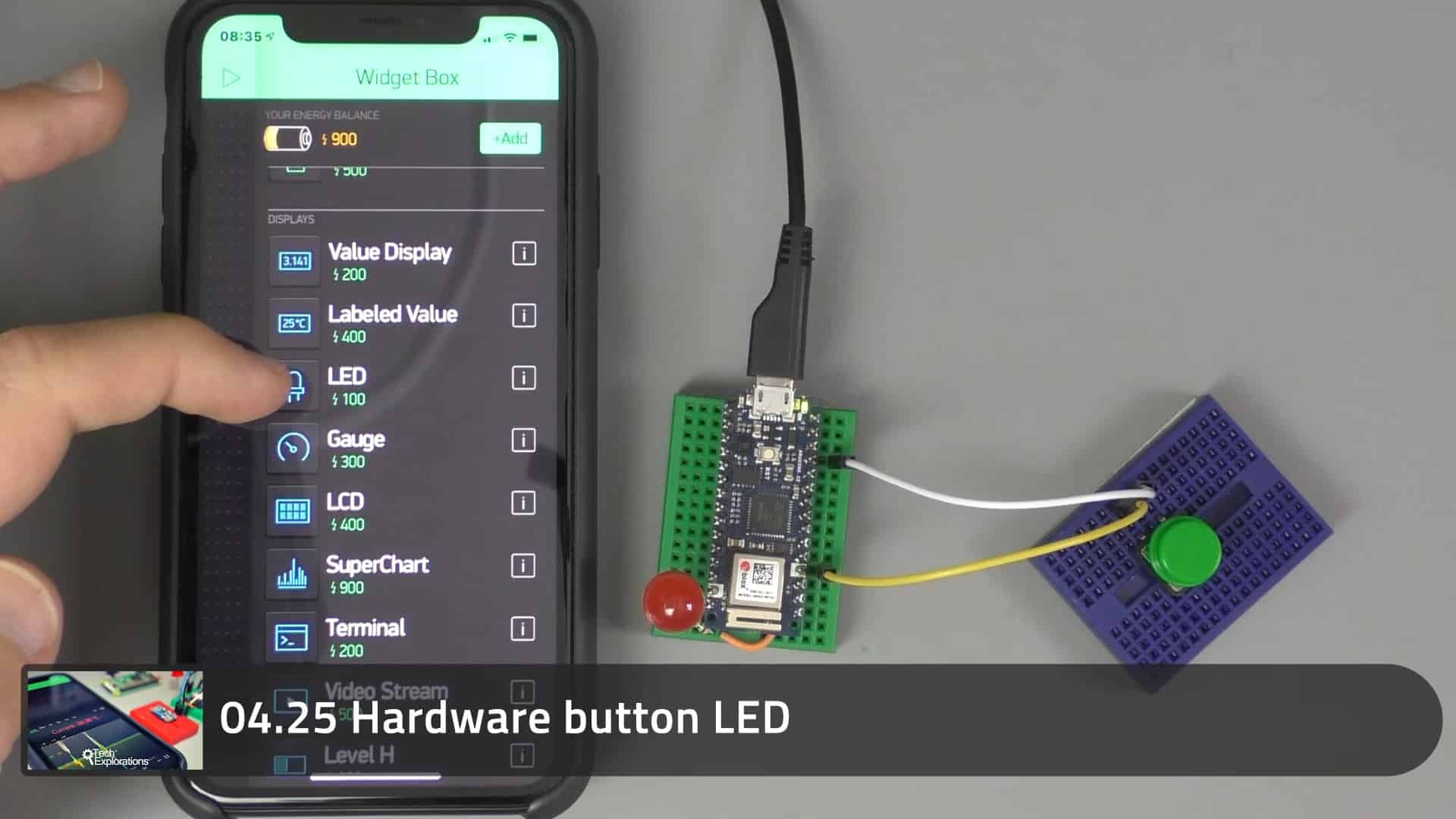
The LED widget of the Blynk set of widgets
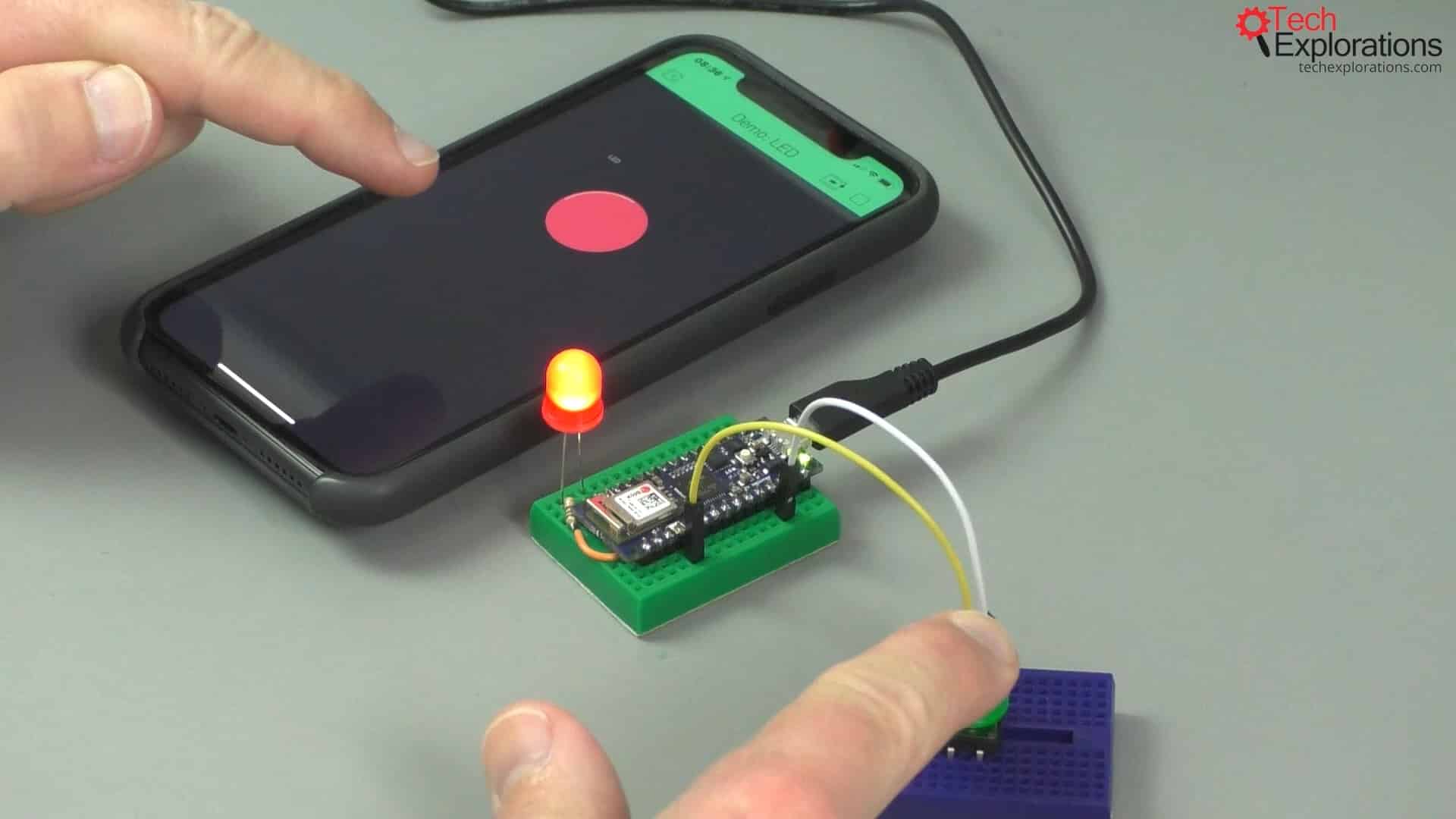
The example I have setup works like this:
When I press a hardware button connected to an Arduino Nano 33 IoT, the LED widget in my Blynk project turns on. When I release the button, the widget LED turns off.
Apart from on and off states, the Blynk LED, just like a real-world LED, also has intermediate states. I can pass a PWM value to a hardware LED and make it fade, make it have a state in between fully on and fully off.
I will show you how to do that in the next article, in which I will use a potentiometer to generate PWM values.

Pressing the button turns the LED on
Properties of the LED
In this article, I will show you how to use the LED widget.
First, you can customise its size and color, as well as the name of the widget.
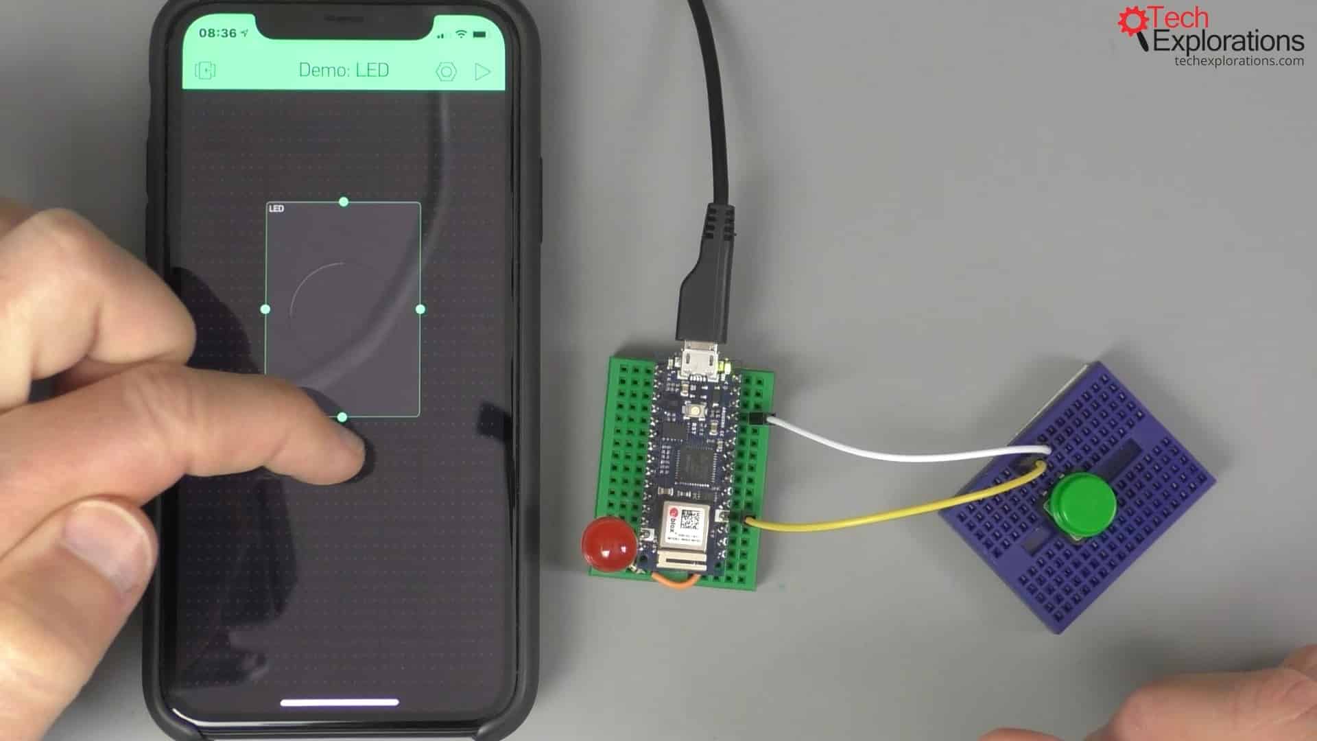
Changing the size of the LED inside Blynk
An LED widget much be connected to a virtual pin. It cannot be connected to an analog or digital pin.
I have connected it to virtual pin 0.
In my demonstration here, I've also attached an external LED that also waits for the button to be pressed, and it turns on as it is the Blynk LED.
I've done that because now you can clearly see the lag, how long it takes for the application to react when I press the button.
As I'm using the Cloud Blynk server, it takes a little bit of time for the communications to take place. In a local private server, there is virtually no noticeable lag.
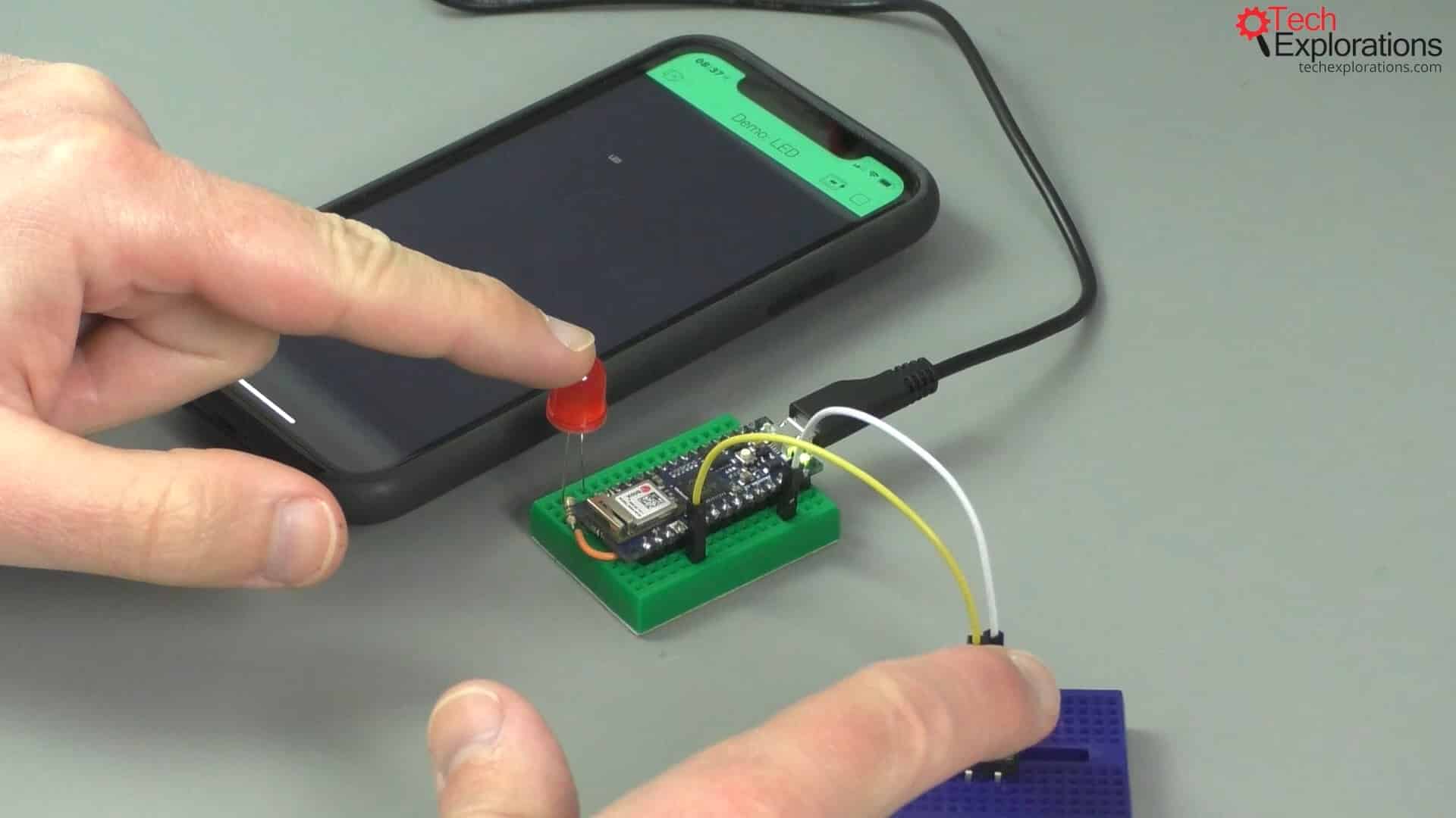
The external hardware LED
The LED sketch
Let's have a look at the sketch below (get it from the course repository):
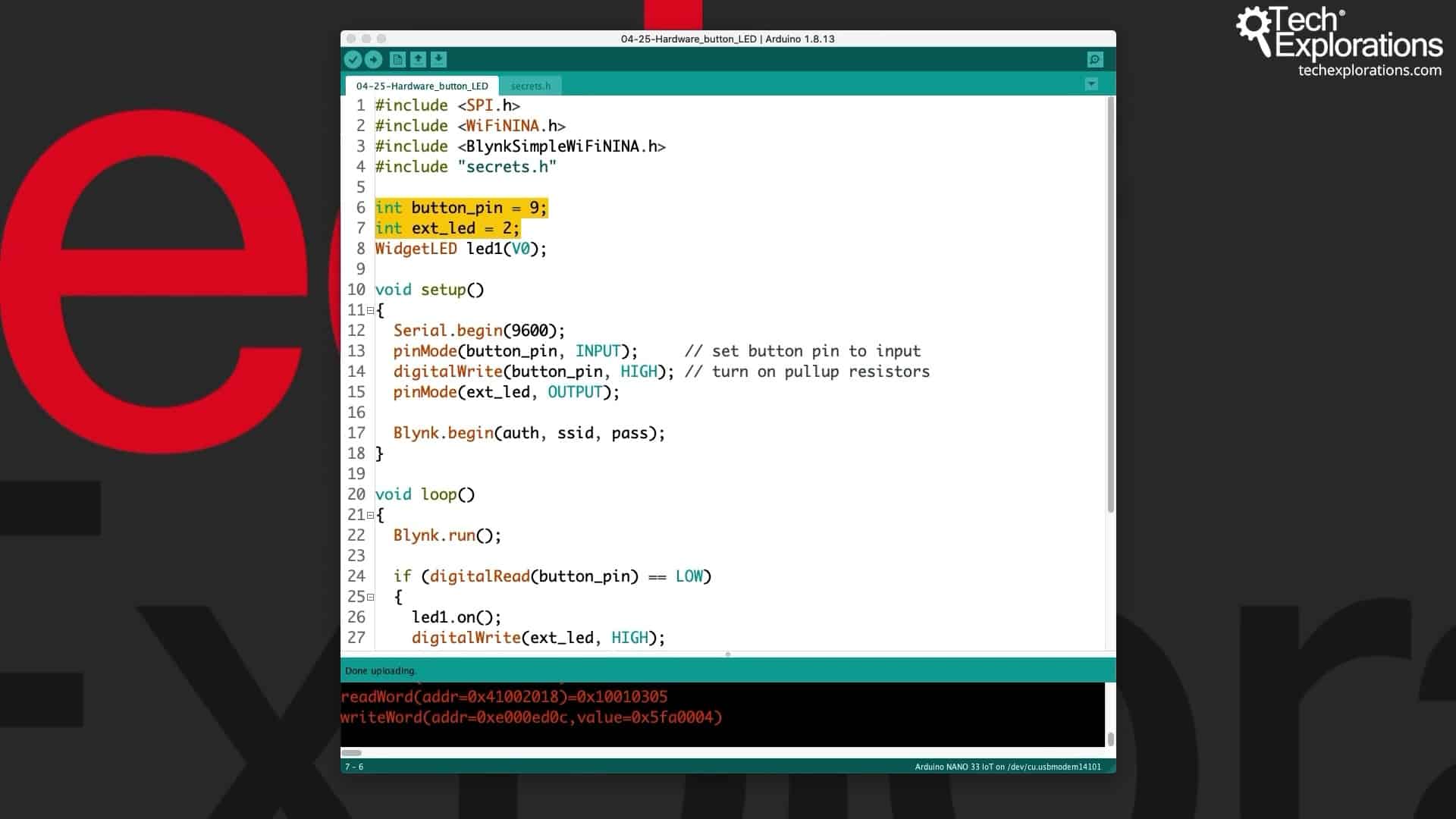
The LED sketch
I have connected the button to digital pin 9, and the external LED to digital pin 2. Here is the schematic:
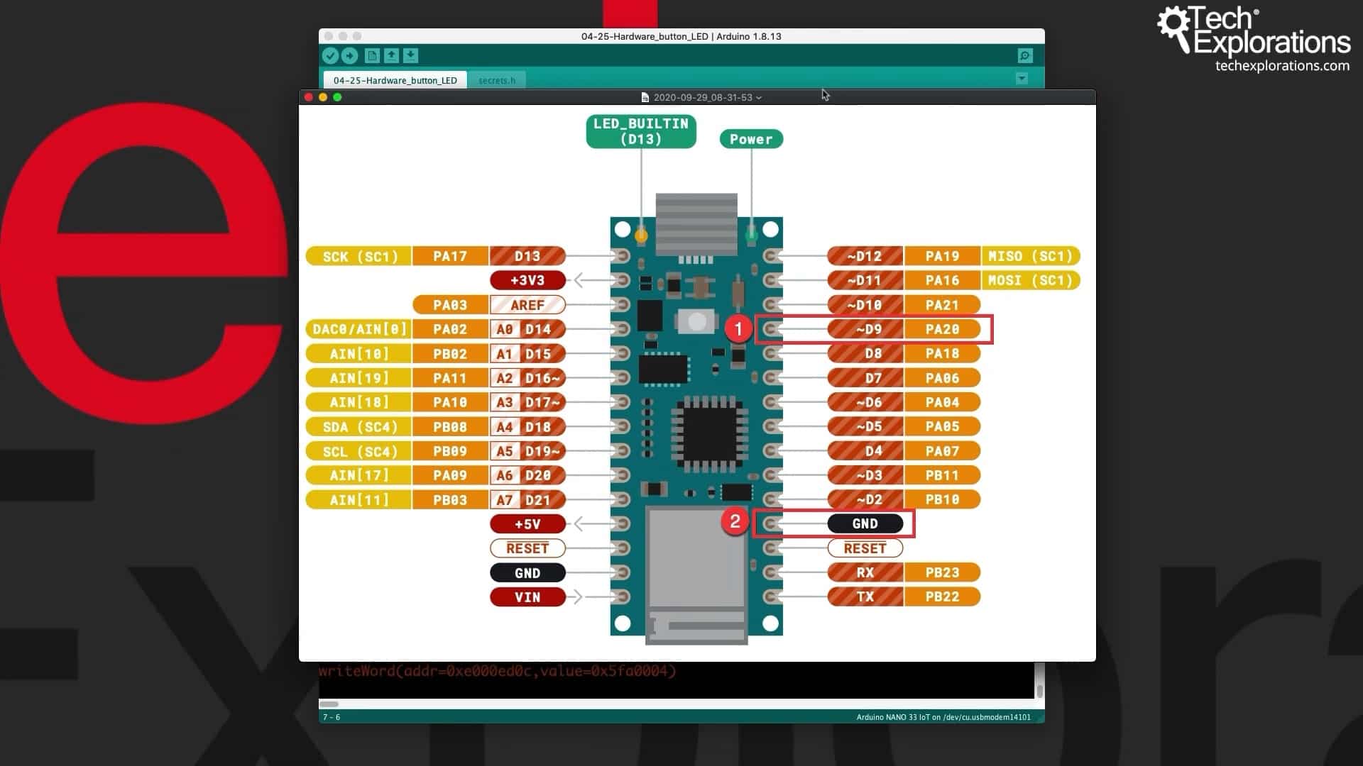
The Arduino pins schematic
In this schematic, you can see that I've connected the button to digital pin 9, and the other side is in ground. I did not include a pull-up or pull-down resistor because I'm doing this in software.
In line eight of the sketch, I have also set up the WidgetLED led1 object, and that is connected to virtual pin 0 (V0).
Inside the setup function, I've got the serial monitor, and then I've got pinMode for the button pin that's an INPUT.
You can see in line 14 that I have turned on the internal pull-up resistor, to save me from having to add a resistor on the breadboard. It makes it a bit easier in the circuit.
For pinMode for the external LED, that is an output, and it's on digital pin 2.
After all that, I start the Blynk object.
Inside the loop function, I constantly call the run function, and then I check the state of the hardware button.
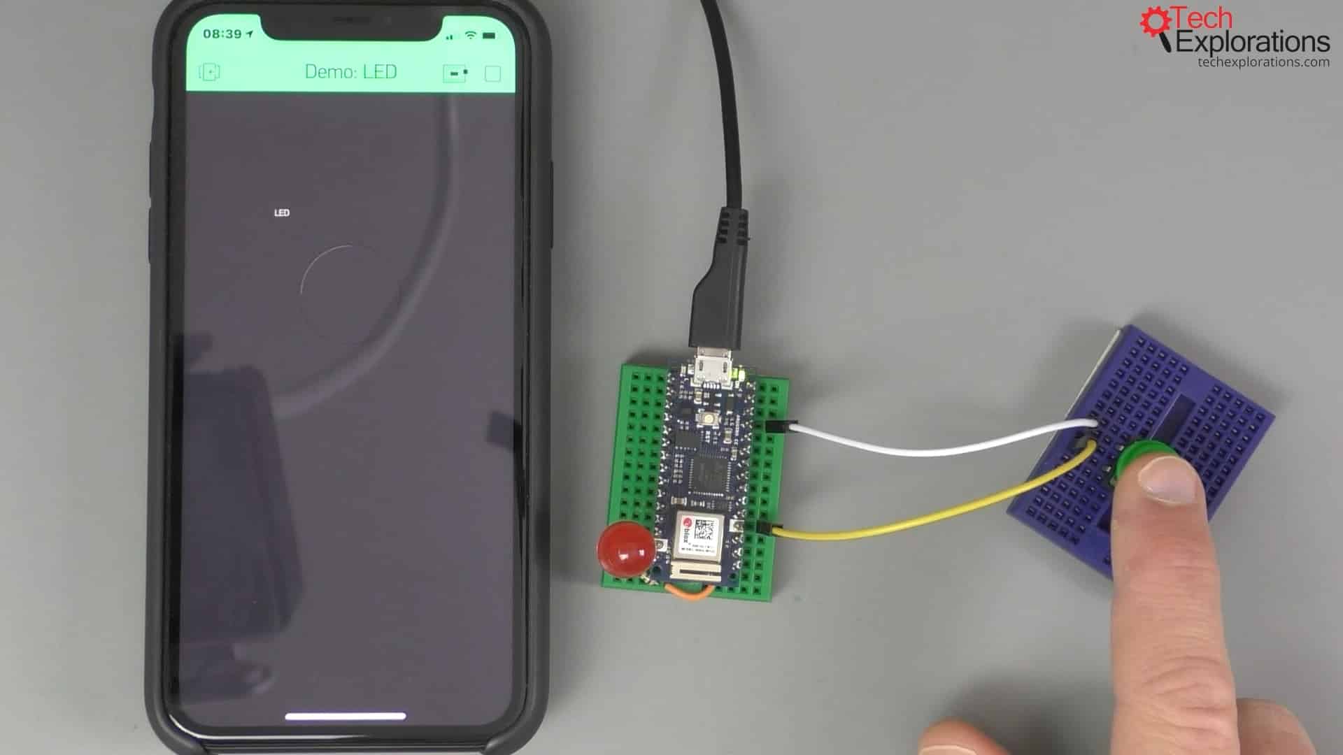
The hardware button
Because I am using the internal pull-up resistor, I want to check if we're at LOW state. When the button is pressed, then digitalRead will return a LOW, and that's how I know that the button is pressed.
When it is pressed, I call the on function of the Blynk LED object, this object right here.
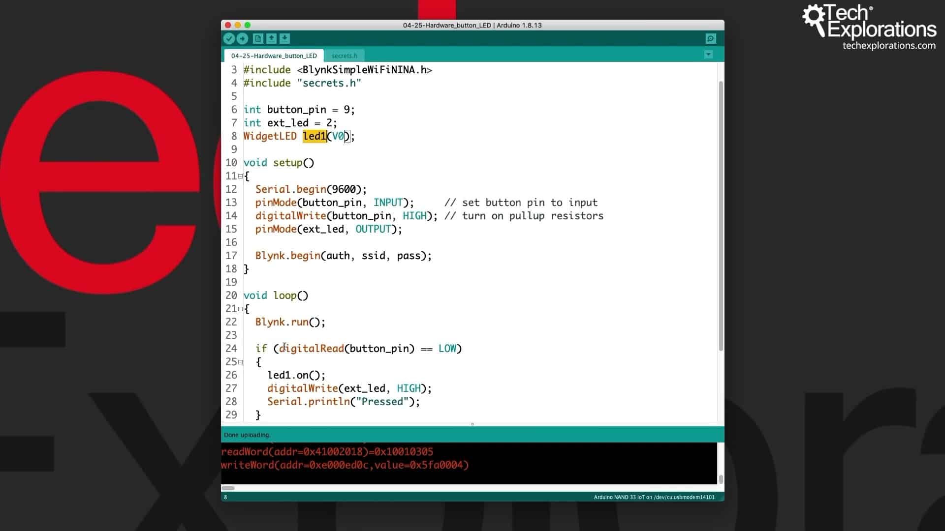
The Blynk LED object
I call the on function, and the Blynk LED turns on.
I also call the digitalWrite function for the external LED to turn that on as well and simultaneously.
If the button is not pressed, then the Blynk LED1 is turned off, and so is the external LED on digital pin 2.
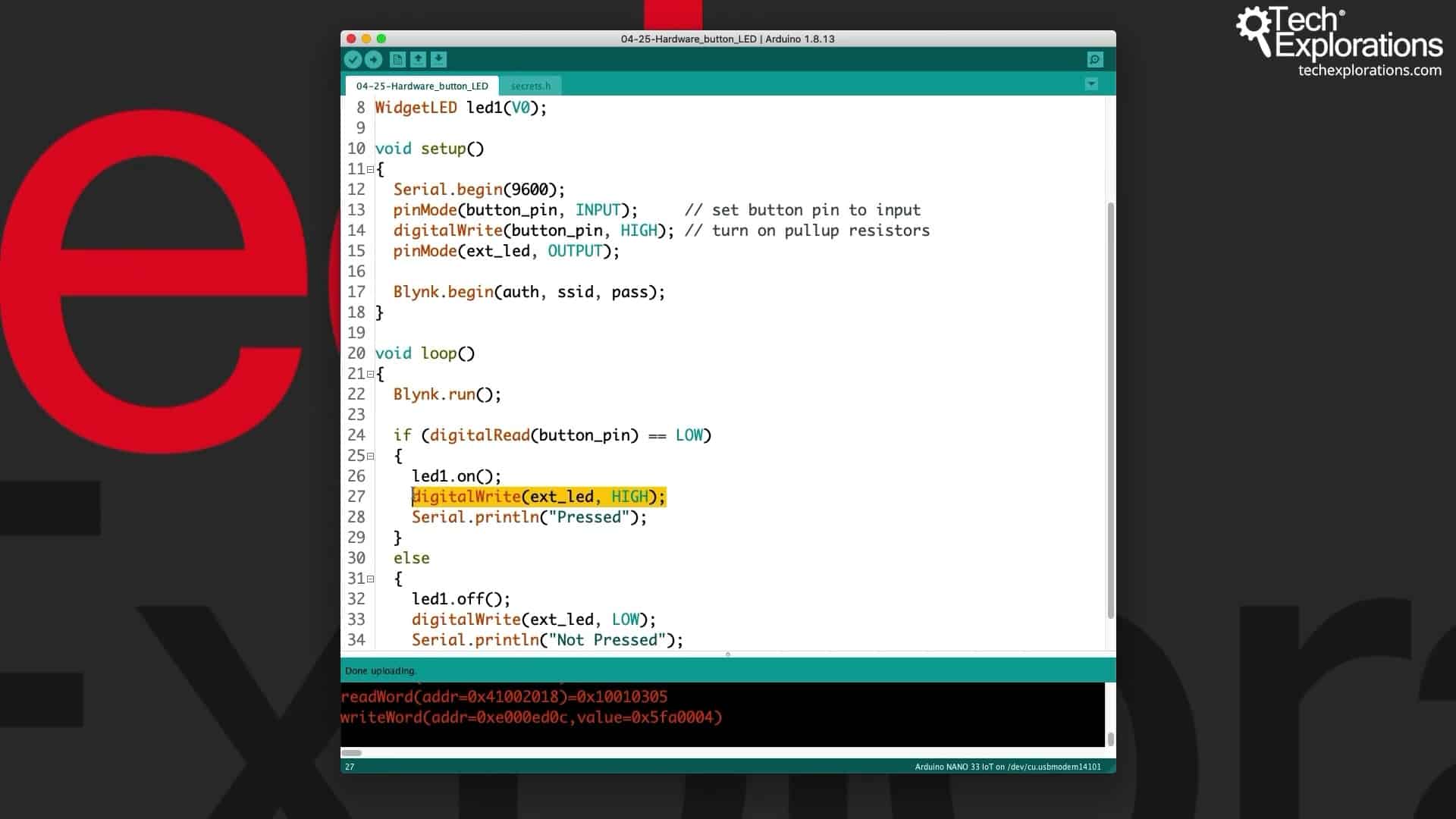
The digitalWrite function
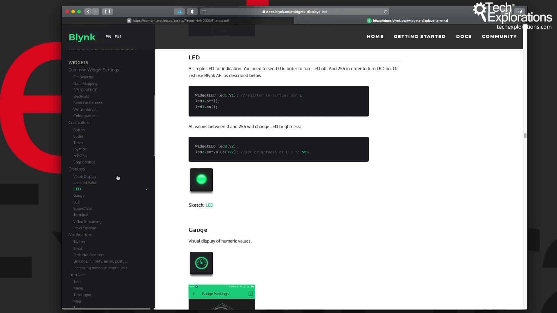
The LED documentation
I also quickly want to show you the LED documentation because it's a good summary of all the available functions. So, here's the LED segment in the Blynk documentation.
You can see how to create the WidgetLED object and attach it to a virtual pin and then the off and on functions for the LED. That's why you need the virtual pin to do that.
It's also possible to send an integer to the WidgetLED, and this is what simulates an in-between state between fully on and fully off that will be a simulated PWM value.
I will show you the effect that this has on the widget LED in the next article.
Conclusion
That's all there is to use the Blynk LED widget.
Of course, you can control the widget without a hardware button. Anything that sends an LED on or off from any other function; it could be part of processing; it could be the timer that triggers the LED widget to turn it on.
It doesn't need to be a hardware button, but in this case, the hardware button makes it easy to demonstrate.
In the next article, I will show you how to use a potentiometer to get the WidgetLED to show in between states a simulated PWM.
Learn Blynk with our video course
Start right now with Arduino Mobile Development with Blynk
This is our comprehensive video course, packed with high-quality video, hands-on mini-projects, and our friendly and supporting community.
Jump to another article
1. What is Blynk?
2. Demo of a simple Blynk project
3. The Arduino Nano 33 IoT
4. Install the Blynk app, create an account
5. Create a new Blynk project
6. How to use a virtual pin
7. Replace the Arduino Nano 33 IoT with an ESP32
8. Button and styled button
9. Hardware button LED
10. Hardware potentiometer LED
11. Vertical and horizontal slider
Last Updated 3 years ago.
We publish fresh content each week. Read how-to's on Arduino, ESP32, KiCad, Node-RED, drones and more. Listen to interviews. Learn about new tech with our comprehensive reviews. Get discount offers for our courses and books. Interact with our community. One email per week, no spam; unsubscribe at any time

