Blynk guide series
Replace the Arduino Nano 33 IoT with an ESP32
Learn how to replace the Arduino Nano 33 IoT with an ESP32 and still implement the same functionality on the Blynk project.
Would you rather watch than read? Here's the video version of this article.
In this article, you will learn how to replace the Arduino Nano 33 IoT with an ESP32 and still use the exact same functionality on the Blynk application.
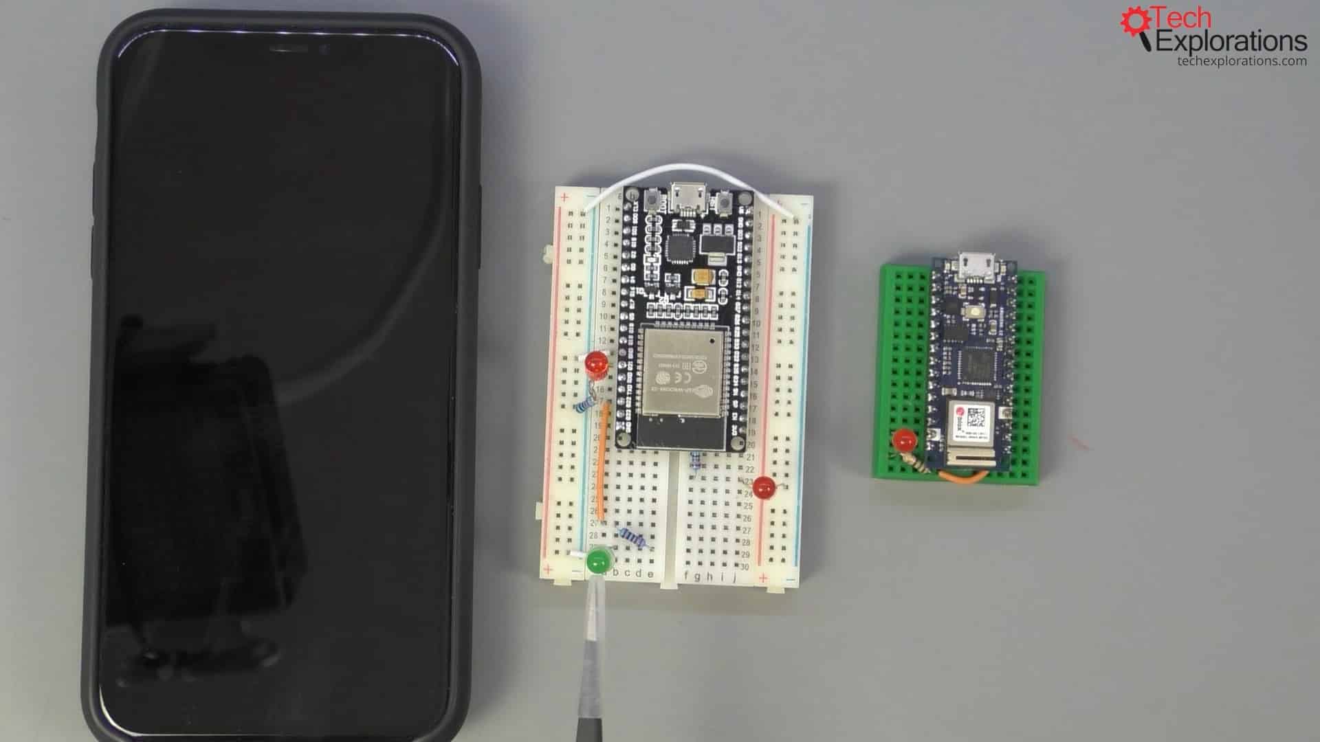
There will be a little bit of rewiring that we will need to do (because the pins to which the LEDs are connected are not the same) and small modifications to the sketch.
But as you will see, these will be very small changes.
Copy the Arduino sketch to the ESP32 sketch
So, first, let's look at the sketches. I've got the sketch that we saw in the previous lecture for the Arduino Nano on the left side and a blank one on the right side.
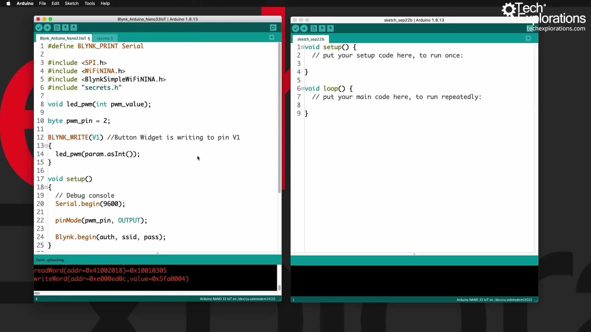
I will begin by copying the whole sketch from the Arduino side and pasting it to the ESP32 side.
I will do the same thing for the credentials, and I will save this new sketch as Blynk_ESP32.
The token will be the same since my ESP32 will be connected to the same Blynk application.
Modify the ESP32 sketch
Now, I will need to make a couple of changes. First, the pin I want to use and control our PWM is shown in the image below. It is connected to GPIO22.
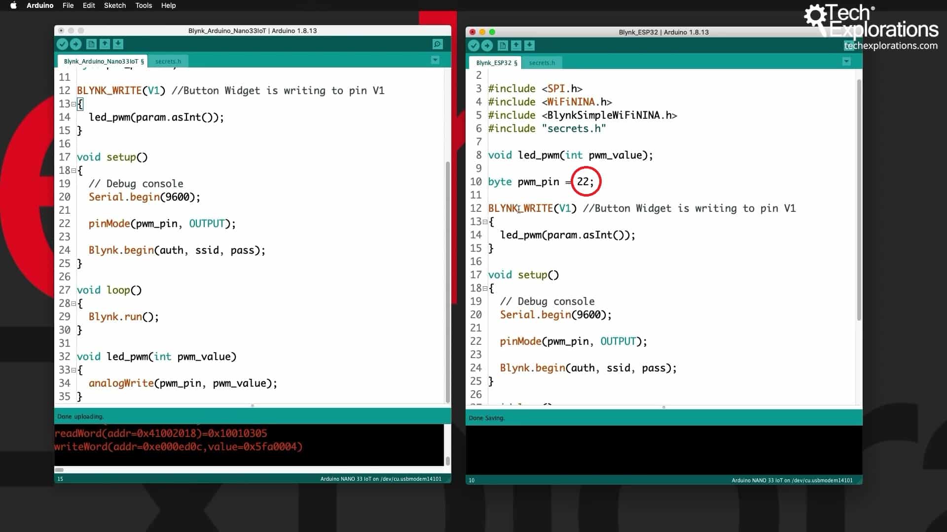
I will change the number 2 in the sketch into a 22. The BLYNK_WRITE(V1) is the one that I'm going to continue to use.
Because the way PWM is implemented in the ESP32 is different from that of the Arduino Nano (at least, the API is different), I need to make a few changes in the actual code.
First, in the led_pwm function, I replace the analogWrite with the ledcWrite.
In the setup function, the way we set up PWM in the ESP32 is like this:
- First, we attach a pin to a PWM channel.
- Then we set up this channel with this frequency and its resolution.
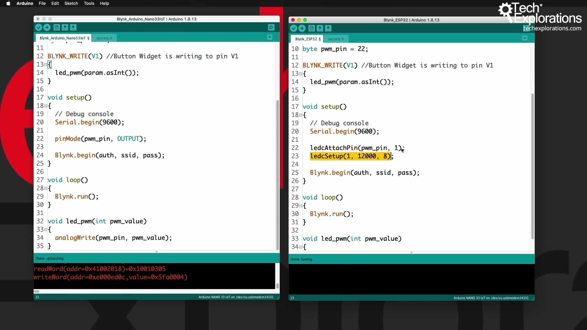
Now we are ready.
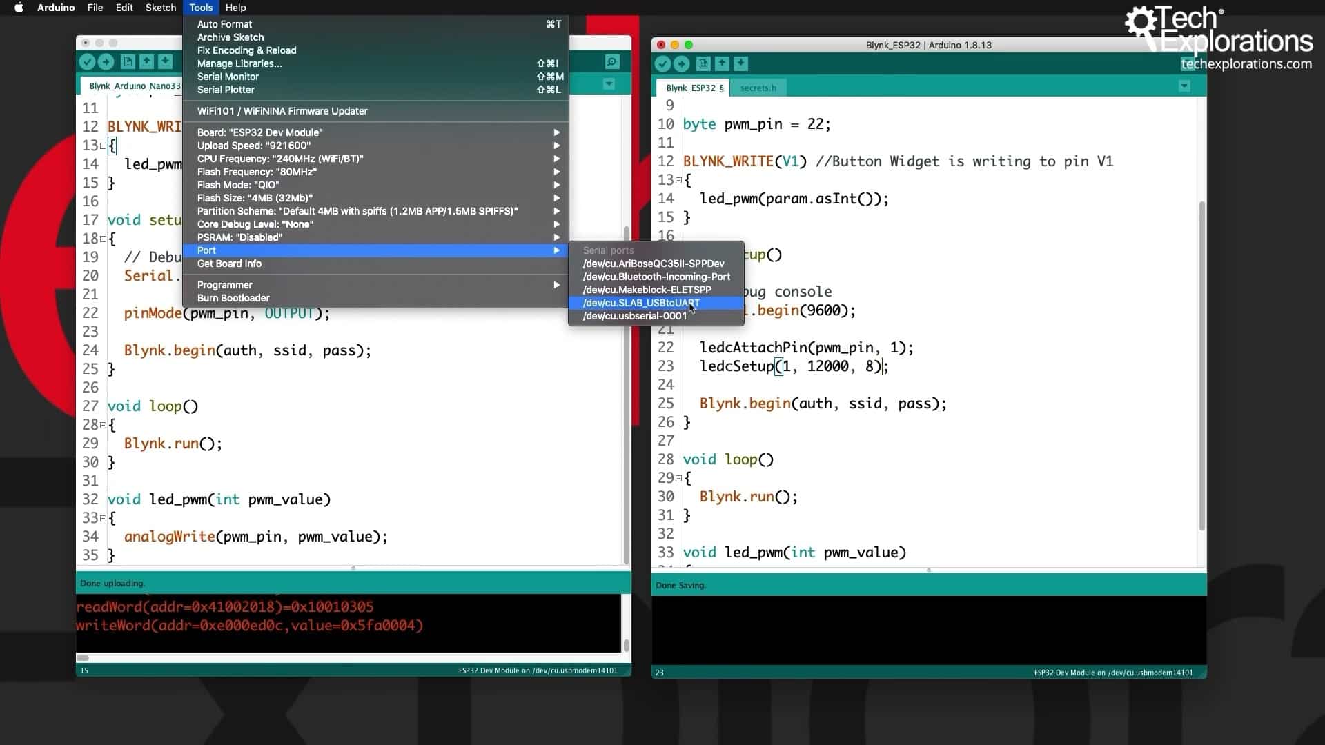
In the Arduino IDE menu bar, click on Tools and change the board to the ESP32 Dev Module.
Next, I will connect the ESP32 and go back to Tools and change the port to the one shown below.
I will then save the sketch and upload it.
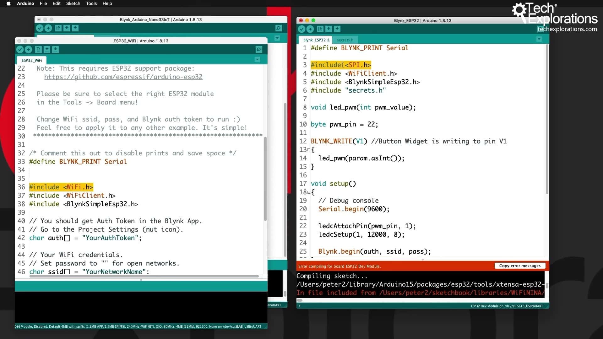
There is one more change that I will need to make, and that is up here.
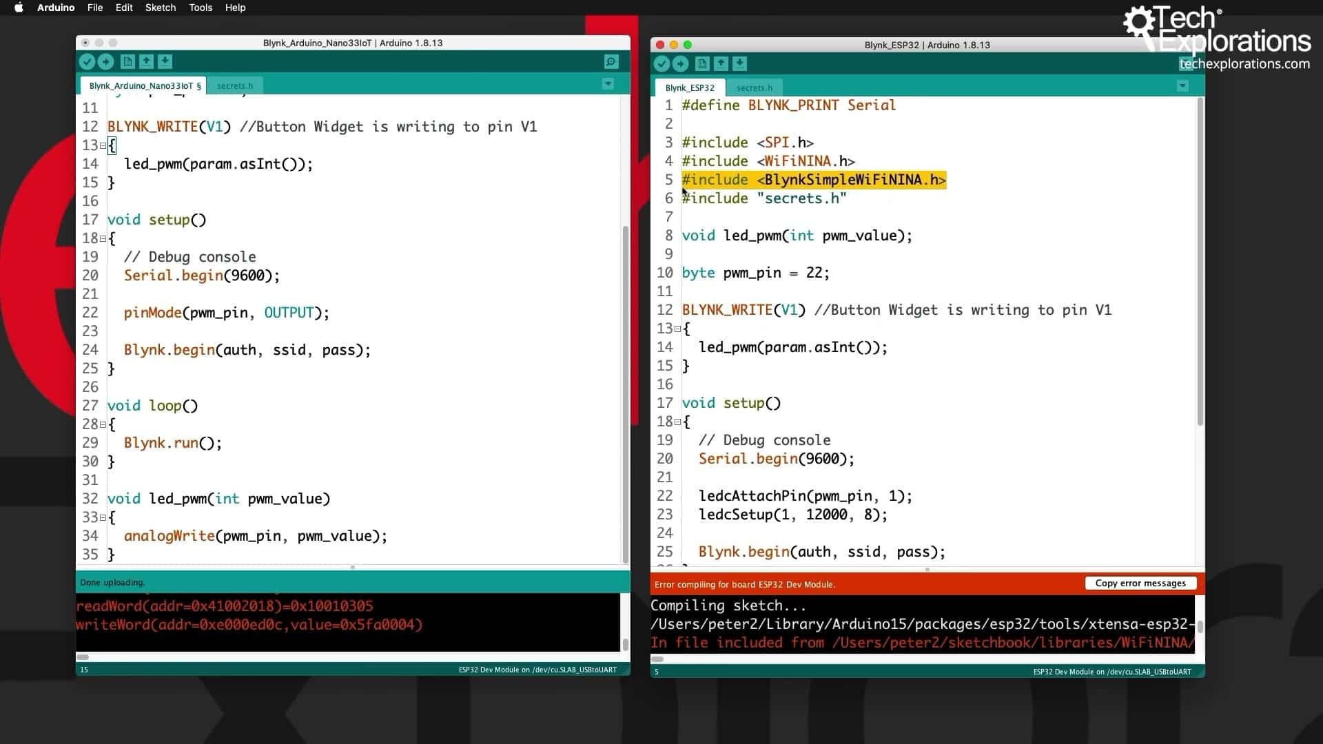
The ESP32 is not using the WiFiNINA chip.
So, to figure out what to use, let's go back to the Arduino Blynk examples under File --> Examples --> Blynk. Select "ESP32_WiFi". You can see this example sketch below (right side).
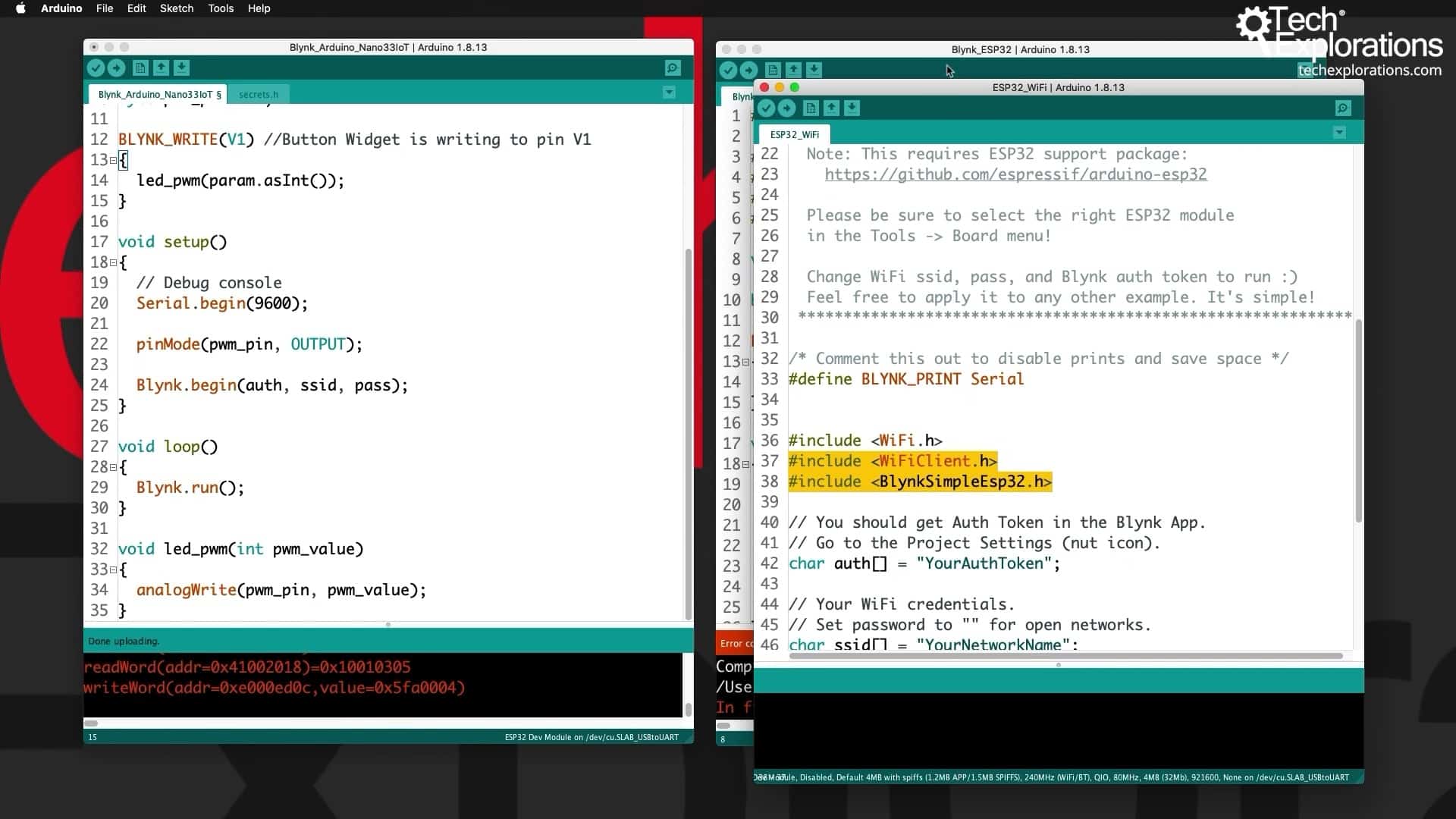
The correct way to do this is to use these two inclusions that I hightlight in the example sketch above and replace the original ("WiFiNINA.h").
All right. So, with these modifications done, let's try again to compile and upload the sketch.
Modify the Blynk application
After the sketch is uploaded, let's go and make a few simple modifications to the application.
At the moment, the application is not running.
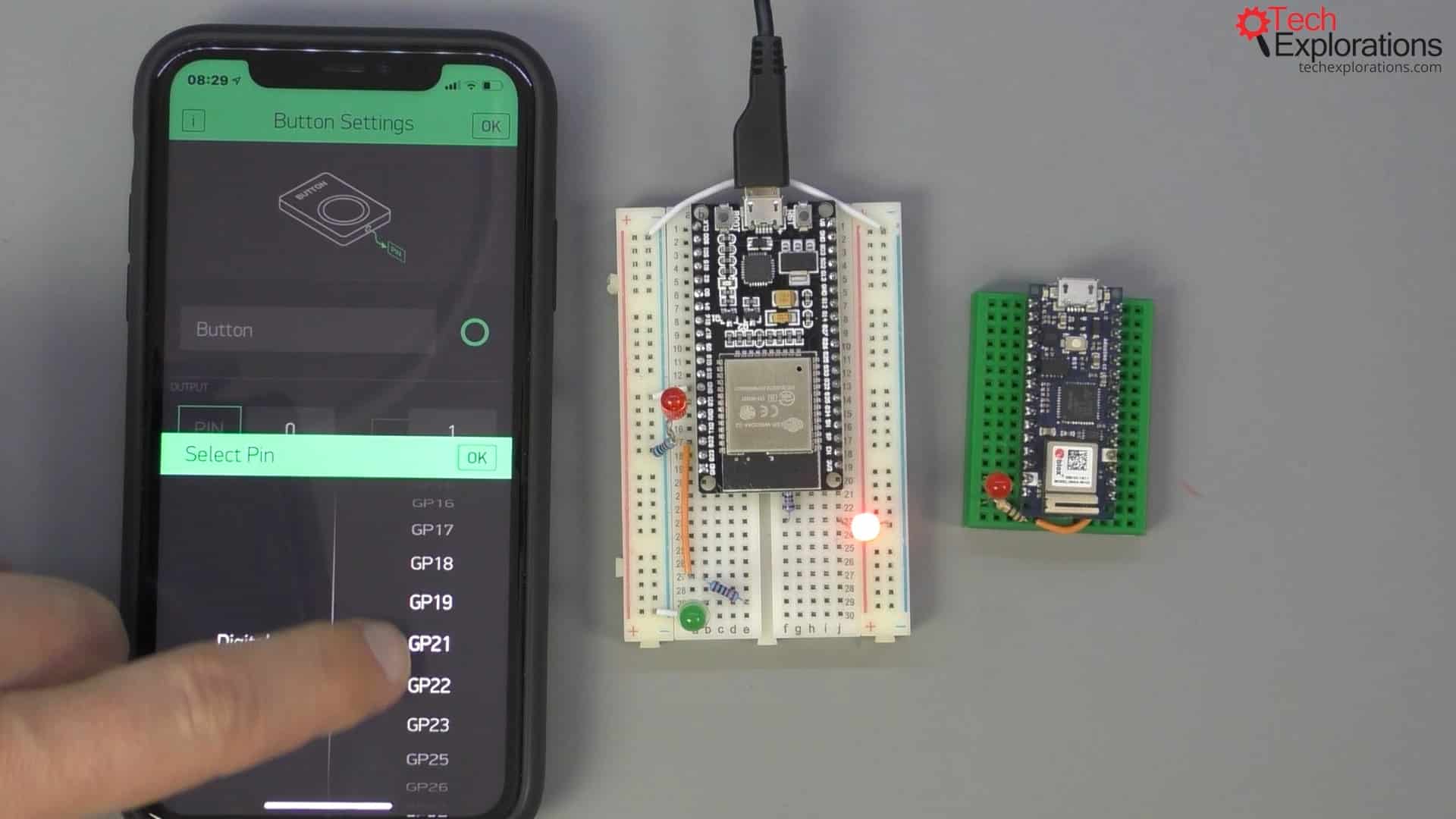
I will "rewire" the button widget so that it connects to pin 21 on the ESP322.
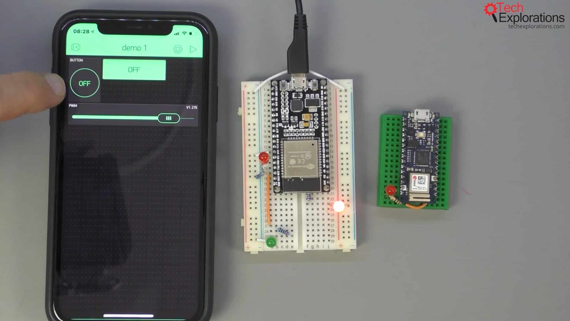
There is, however, another change I want to make before that.
At the moment, the Blynk project is configured with the Arduino MKR1000 as a target. Since I am now targeting the ESP32, I must change the device target in the project.
Go into the app's configuration and change the device to the ESP32 Dev Board and tap "OK." The authentication token remains the same.

Next, go back to the application and reconfigure the button widget (when you change the target device, any widgets connected to the old device loose their digital and analog pin mappings).
Connect the button widget to digital pin GPIO21.
Now, I've got the correct mappings.
Start the project (press "play") and make sure that we have control of the LED.
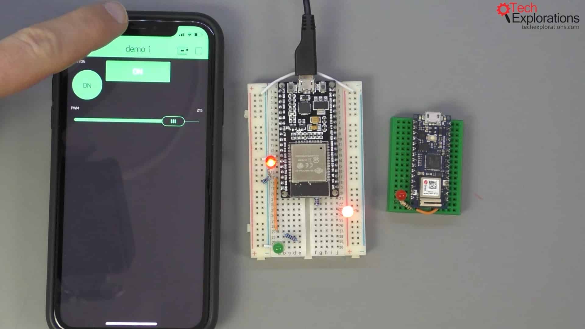
Now, I will control the intensity of the light coming out of the greed LED.
I will stop the application and configure this to be V1, which is already V1 and an 8-bit value from 0 to 255.
Because I'm working with a virtual pin for this widget, I didn't need to remap it between the two devices.
So, I press play, and there's the light controlled via the PWM using the slider.
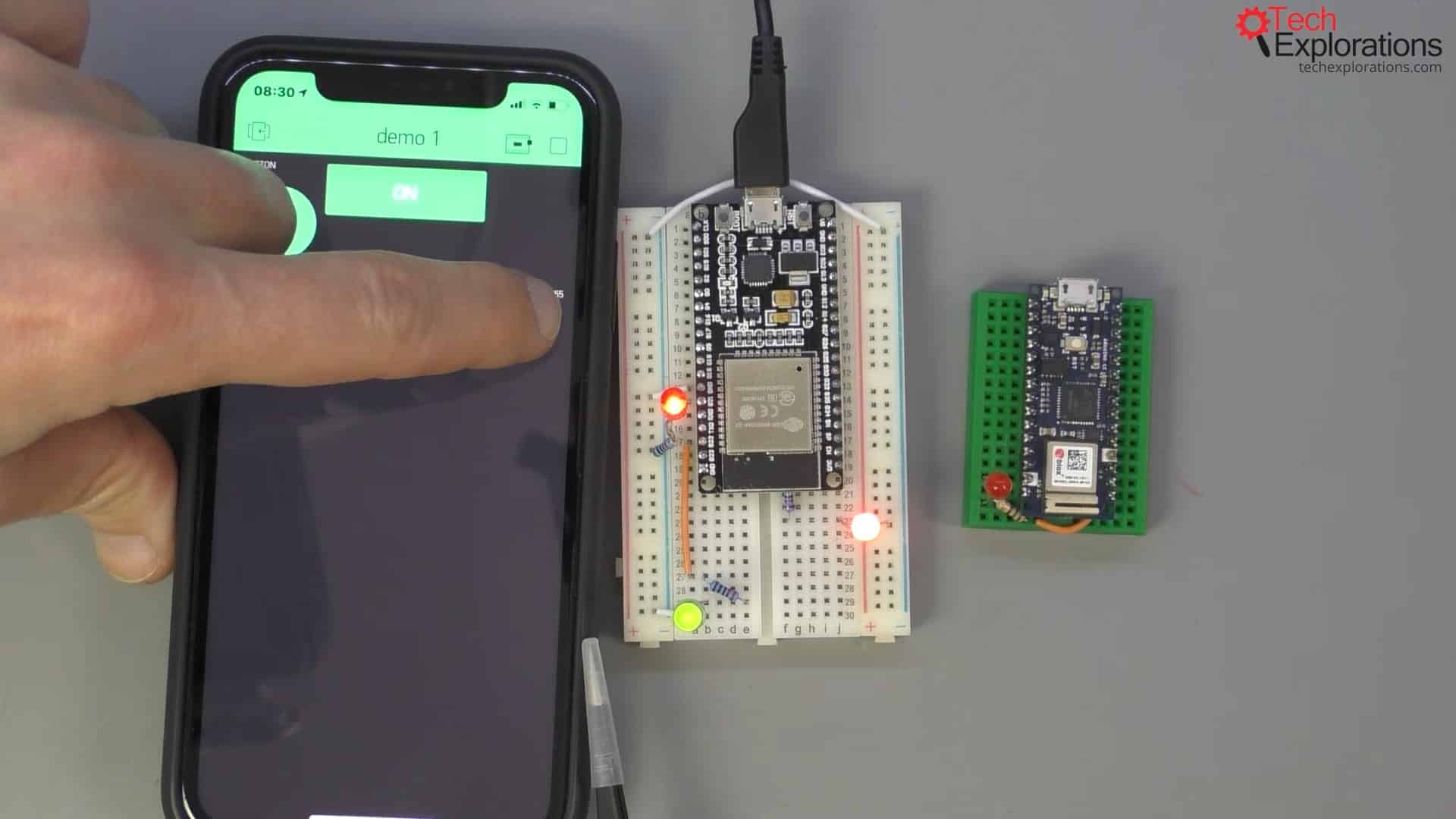
The energy balance indicator
Before I conclude this part of the guide, I want to show you one more thing.
Notice at the top of the widget box the energy balance indicator.
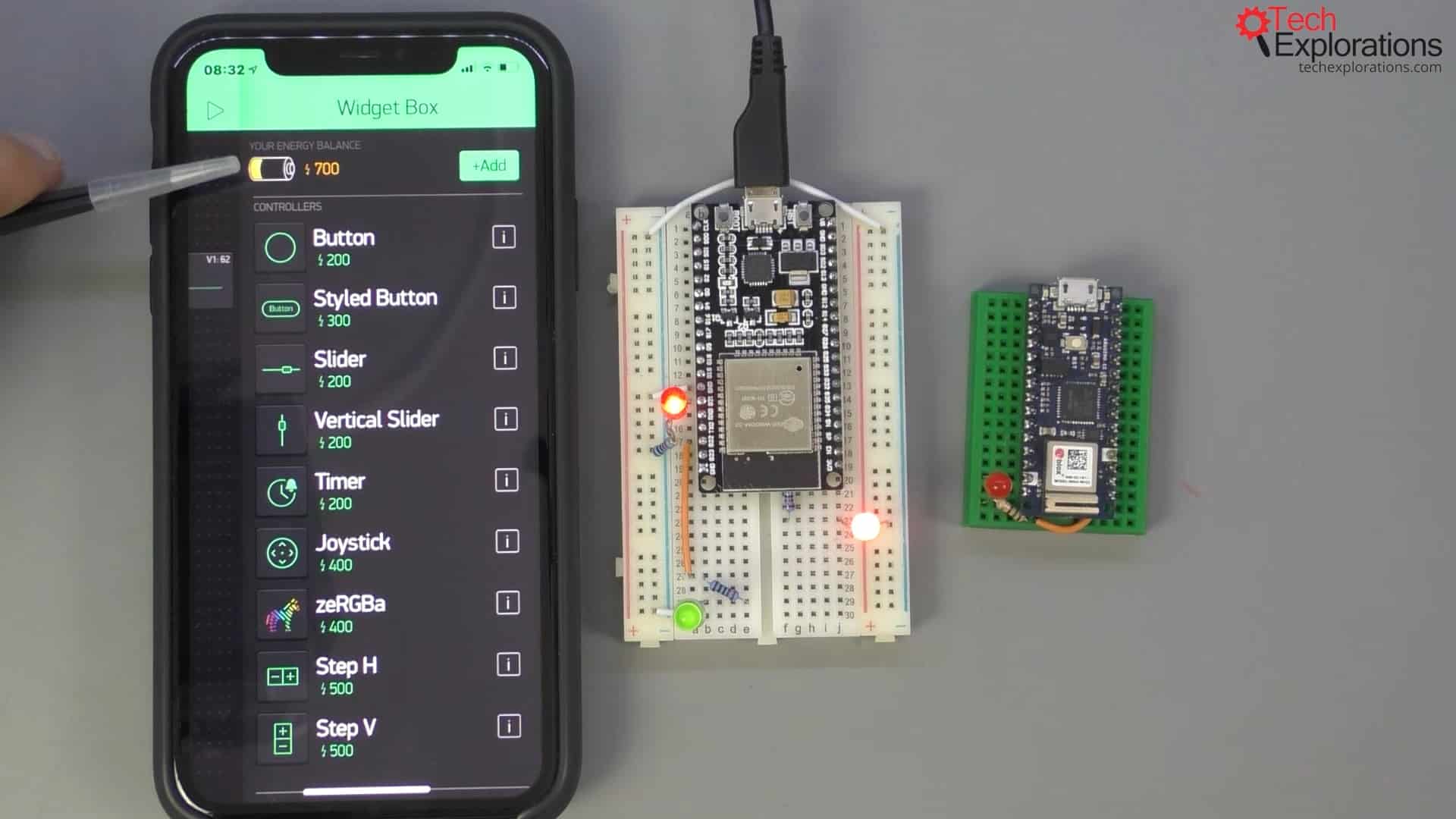
At the moment, I've got 400 energy units. In Blynk, an "energy unit" is similar to currency. You exchange energy units for widgets. For example, if I delete the styled button, my balance increases, allowing me to add some other widget into my application.
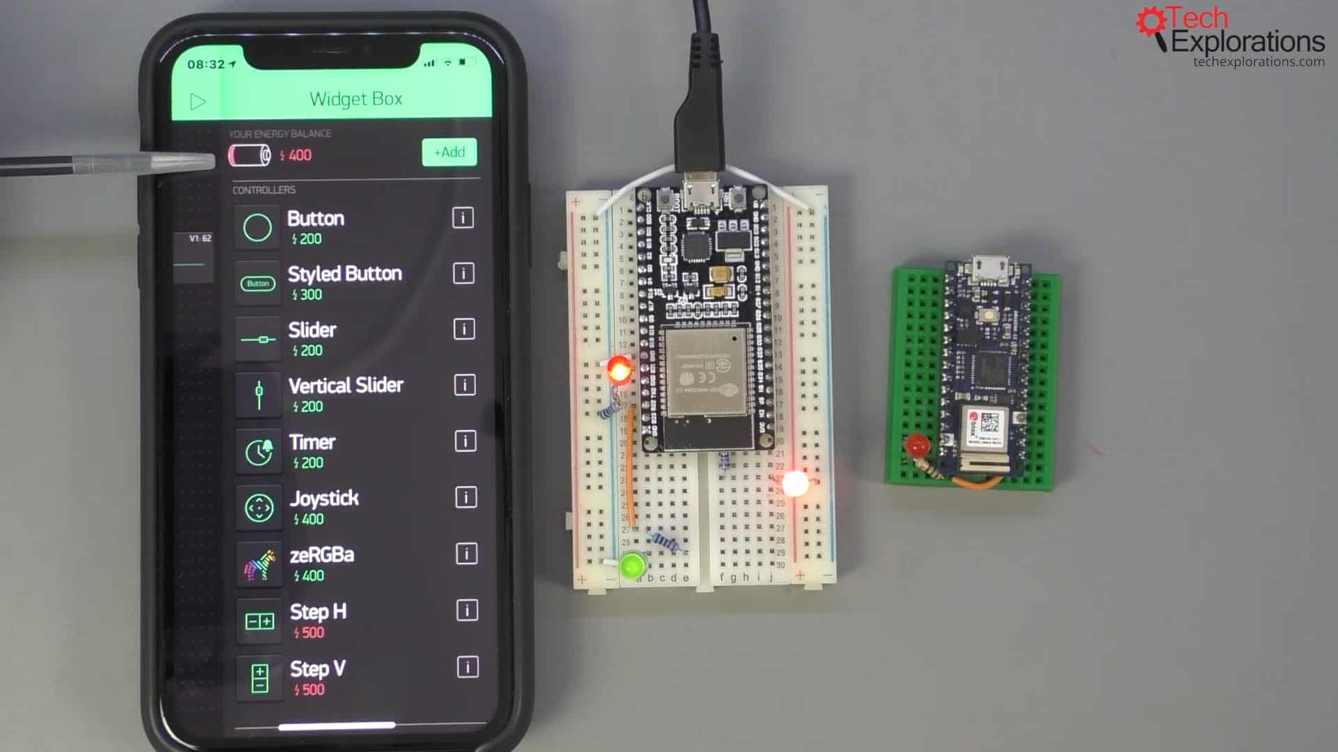
The energy balance indicates how many widgets or how much complexity you can add to your project. There is a limit to how much energy you get when you use the cloud Blynk server.
This limit is totally up to you and customizable if you setup and use a private server.
But, when you use the cloud server, you should be aware that your applications can only have as many widgets as you have energy balance available. Every widget has its own energy cost displayed so that you know what you can afford.
Conclusion
With this set of articles you learned how you can set up your Blynk working environment and how easy it is to jump between devices and program devices without much effort.
In the next few articles, you will learn how to use some of the most common Blynk widgets.
Learn Blynk with our video course
Start right now with Arduino Mobile Development with Blynk
This is our comprehensive video course, packed with high-quality video, hands-on mini-projects, and our friendly and supporting community.
Jump to another article
1. What is Blynk?
2. Demo of a simple Blynk project
3. The Arduino Nano 33 IoT
4. Install the Blynk app, create an account
5. Create a new Blynk project
6. How to use a virtual pin
7. Replace the Arduino Nano 33 IoT with an ESP32
8. Button and styled button
9. Hardware button LED
10. Hardware potentiometer LED
11. Vertical and horizontal slider
Last Updated 3 years ago.
We publish fresh content each week. Read how-to's on Arduino, ESP32, KiCad, Node-RED, drones and more. Listen to interviews. Learn about new tech with our comprehensive reviews. Get discount offers for our courses and books. Interact with our community. One email per week, no spam; unsubscribe at any time
