Blynk guide series
Demo of a simple Blynk project
In this guide page I will show you what you're going to accomplish by the end of this series.
Would you rather watch than read? Here's the video version of this article.
We will begin with the Arduino Nano because it's got a built-in Wi-Fi and built-in LEDs that we can use to play around with some of the most basic and simple widgets in Blynk. Later, I'm going to migrate our application onto the ESP32 to show you how easy it is to jump from one device to the other.
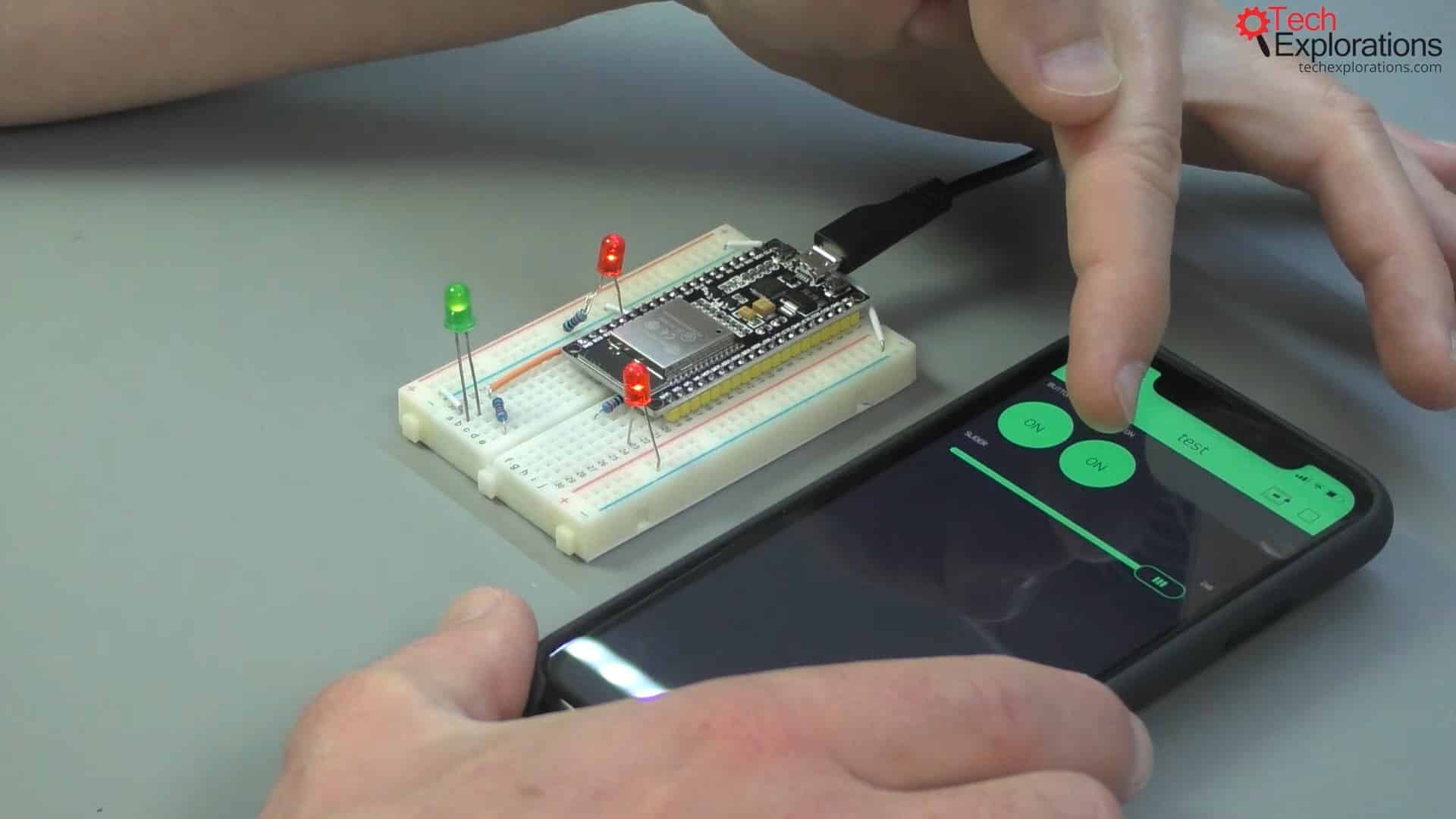
Below is an example of a very simple circuit that is based on a generic ESP32. Since it doesn't even have any built-in LEDs that I can control this is what I've done: I've connected an LED to a 3.3 volts pin to indicate that the power is on and I've got another two LEDs that I will use to control the Blynk application. I will connect the first LED to GPIO21 and the second one to GPIO22. Nothing fancy here.
An example of a simple circuit based on a generic ESP32
Start with the public Blynk server
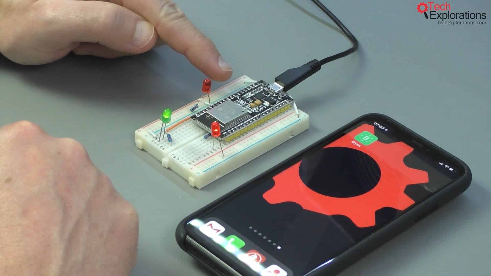
Next, we will be using the public Blynk server instead of installing a private server on a Raspberry Pi. That's something that we're going to do in subsequent sections. A public Blynk server is the easiest one with which to begin.
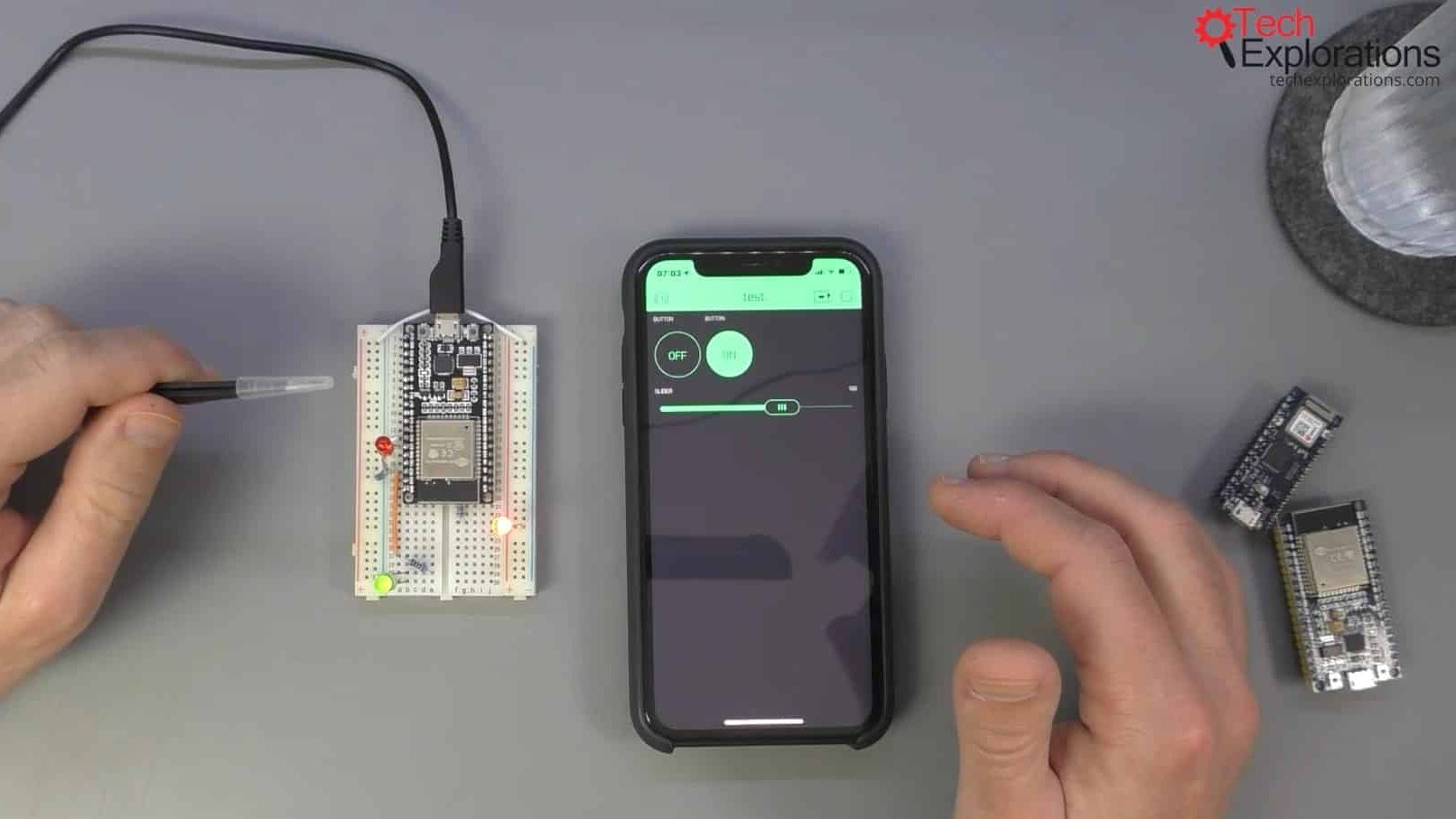
The new Blynk app with two buttons and a slider that control two LEDs on the ESP32
Control the red LED with a button
I've got my Blynk application running on my phone. When I press the button (shown in the picture) the red LED turns on momentarily, at least for as long as I'm pushing the button.
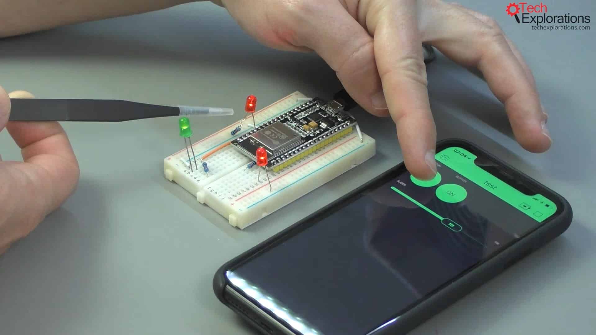
Pressing the button turns on the red LED for as long as the button is being pushed
Control the green LED with a slider
I've also got a slider that I can use to send PWM values to the green LED and control its brightness.
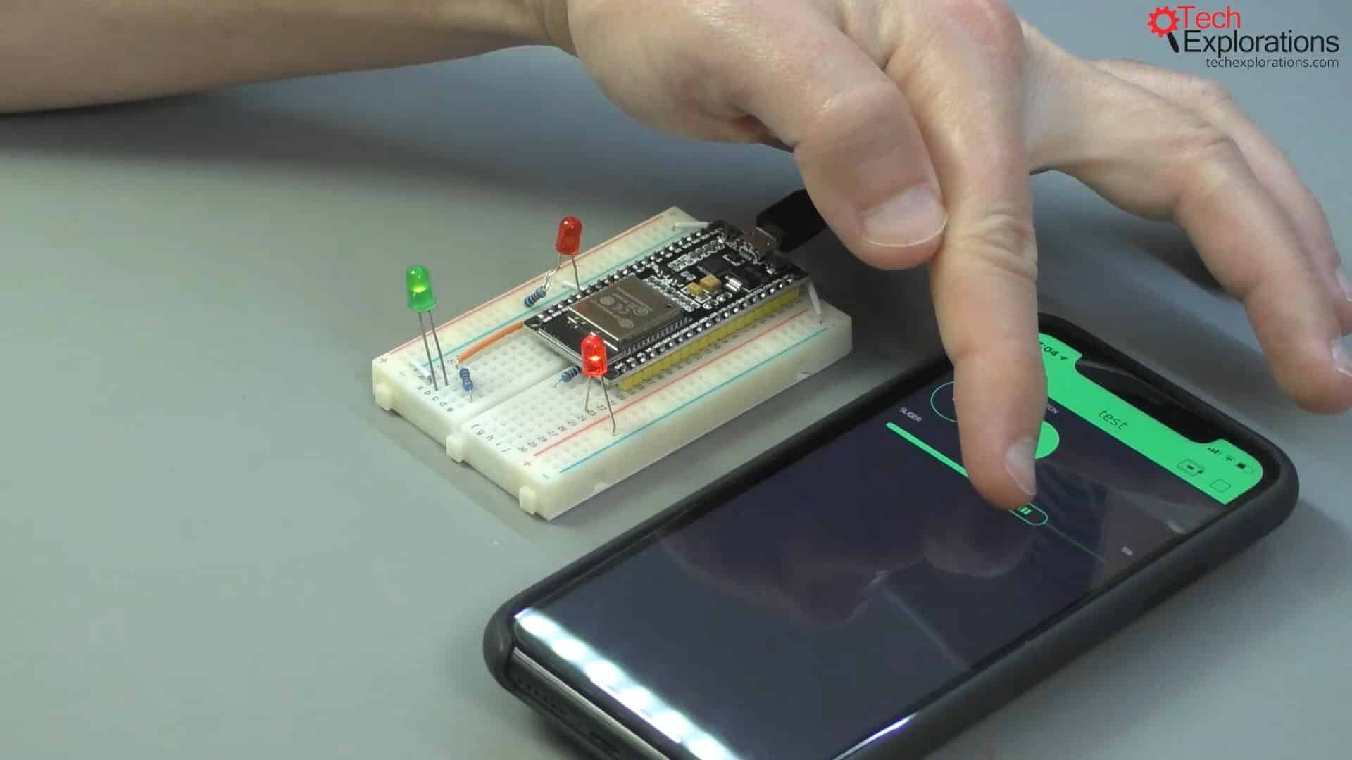
Using a slider controls the brightness of the green LED
Control the red LED with a switch button
I've got another button, which I've configured as a switch. When I change its state, it stays with this new state. Now, I'm going to connect it to the GPIO21 to control that. Instead of having the red LED stay on for as long as I'm pressing the button, I'm going to make a little change: I've got that button connected to GPIO22, but I'm going to switch it to GPIO21. It says busy, but that's okay.
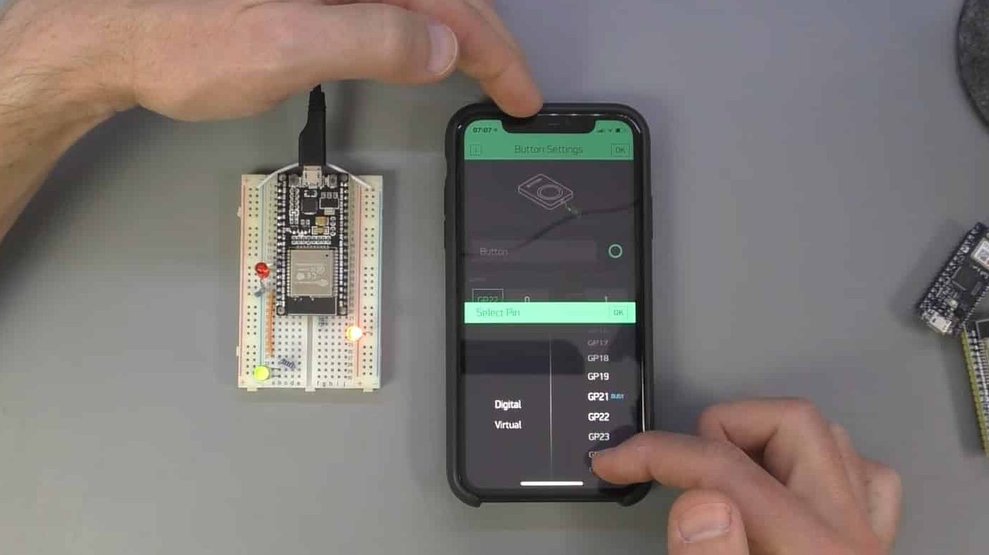
Switching the connection to GPIO21
I press the play button again, and this is what happens: As I'm pressing the switch now (a button configured as a switch) the red LED stays on.

The red LED stays on while the switch button is on
Conclusion
You see how easy it is to make such a change without having to make any changes and re-flash the sketch on to the ESP32. There's a lot of functionality that we can implement directly onto the Blynk application without requiring any modifications to the Arduino sketch that is running on the ESP32. These changes relate to the control of the GPIOs or of the Arduino pins
The above was simply a quick demonstration of what you will have achieved by the end of this series, arguably with very little written code. I will be using templates and then apply minimal changes to the example sketches in the templates.
Learn Blynk with our video course
Start right now with Arduino Mobile Development with Blynk
This is our comprehensive video course, packed with high-quality video, hands-on mini-projects, and our friendly and supporting community.
Jump to another article
1. What is Blynk?
2. Demo of a simple Blynk project
3. The Arduino Nano 33 IoT
4. Install the Blynk app, create an account
5. Create a new Blynk project
6. How to use a virtual pin
7. Replace the Arduino Nano 33 IoT with an ESP32
8. Button and styled button
9. Hardware button LED
10. Hardware potentiometer LED
11. Vertical and horizontal slider
Last Updated 3 years ago.
We publish fresh content each week. Read how-to's on Arduino, ESP32, KiCad, Node-RED, drones and more. Listen to interviews. Learn about new tech with our comprehensive reviews. Get discount offers for our courses and books. Interact with our community. One email per week, no spam; unsubscribe at any time
