Blynk guide series
Hardware potentiometer with LED widget
Learn how to control a Blynk LED widget using PWM values generated by a potentiometer.
Would you rather watch than read? Here's the video version of this article.
The Potentiometer connections
In this demonstration, use a potentiometer to control an LED widget.
The middle pin of the potentiometer is connected to analog pin 0 on the Arduino Nano. The other two are connected to the GND and 3.3V pins.
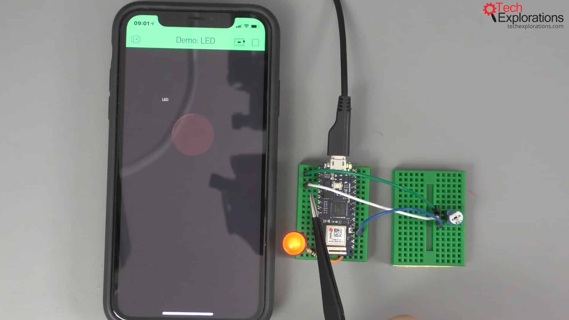
Here is the schematic:
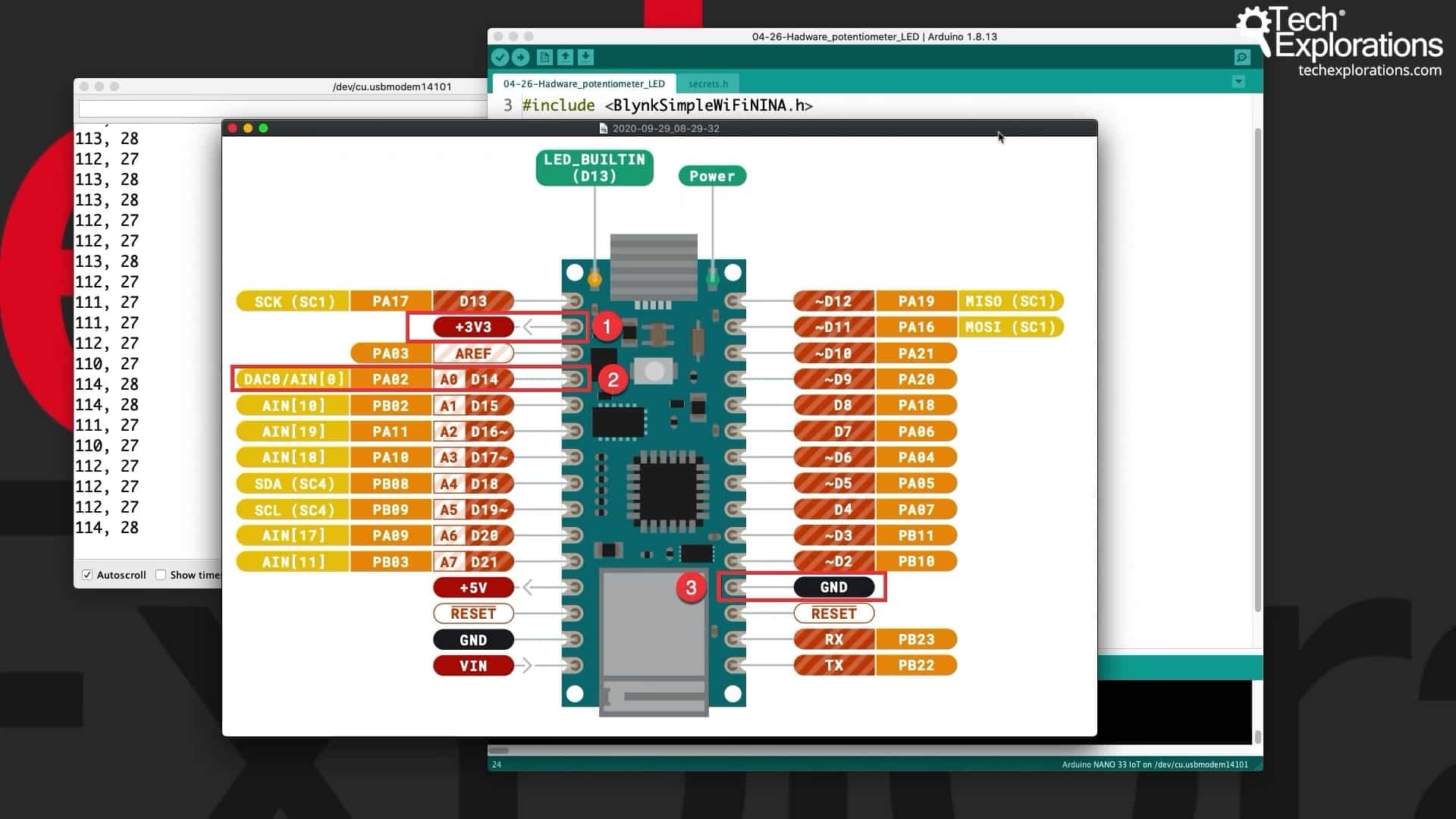
The Arduino Nano 33 IoT pins
In this demonstration, I use the same LED as in the previous article. In the picture below you can see that it's configured to connect to virtual pin 0 (V0). Let's run it again.
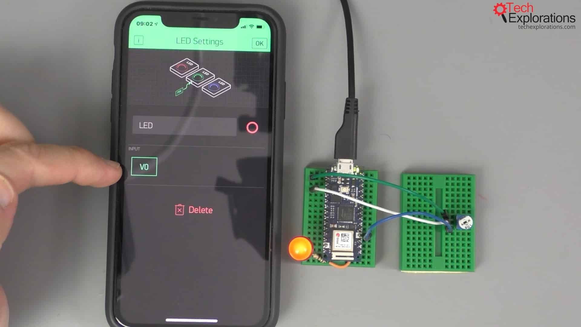
Virtual pin 0 configuration
The Potentiometer sketch
Here is my sketch (get it from the course repository):
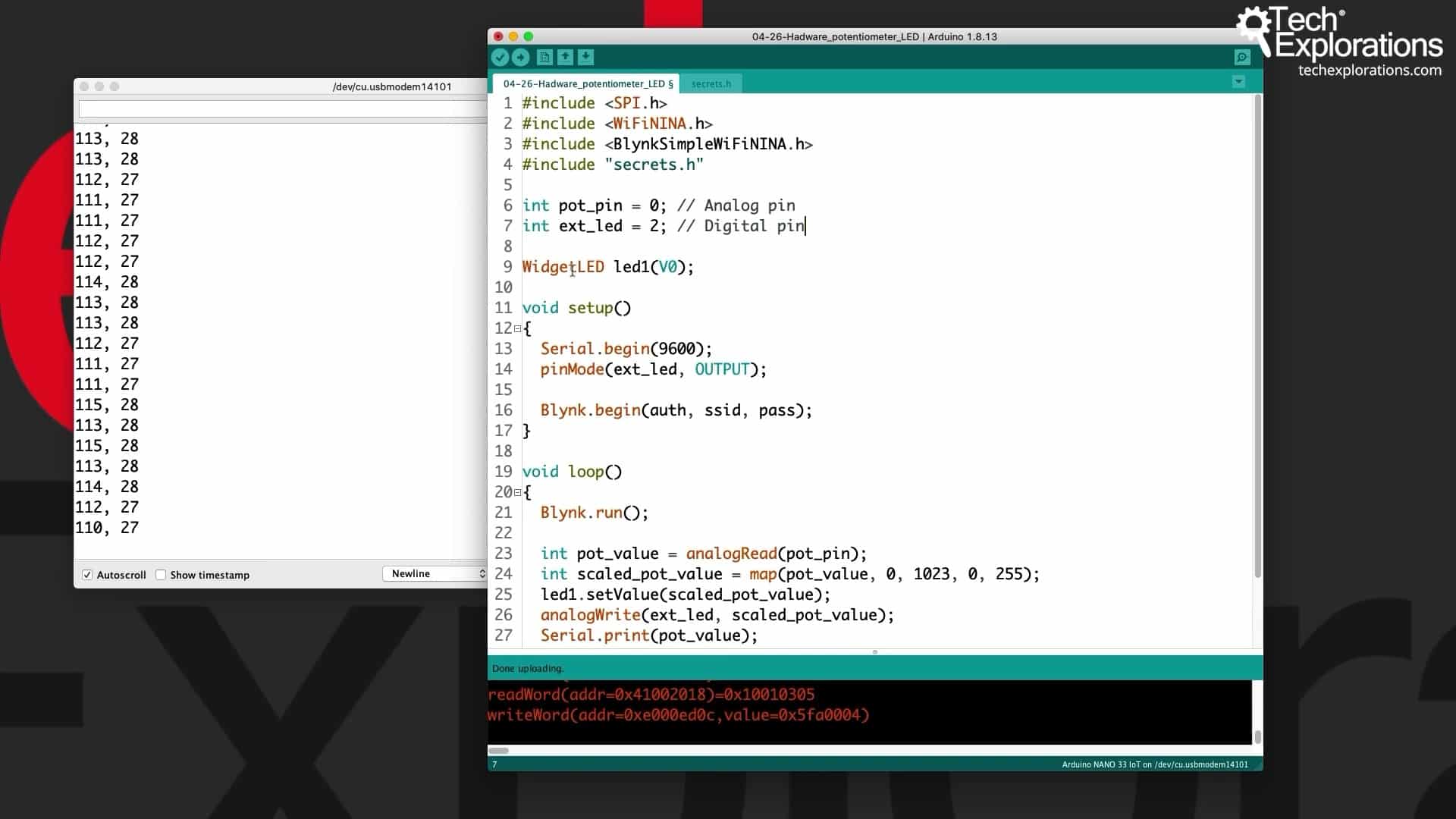
The Potentiometer sketch
The sketch, again, is fairly simple as you would expect.
The potentiometer is connected to analog pin 0. I've got my external LED for validation, and it's connected to digital pin 0. The first one is Analog pin and the second one is, of course, Digital pin. I've got my WidgetLED called led1 connected to virtual pin 0.
In the setup function, I set the external LED to be an output, and I start the Blynk object.
All the work happens inside the loop function, where I call the run function of the Blynk object.
First, I get a reading of the analog pin for the potentiometer that gives me a value that goes from 0 to 123. That's the default analog input resolution for the Arduino Nano (10 bits).
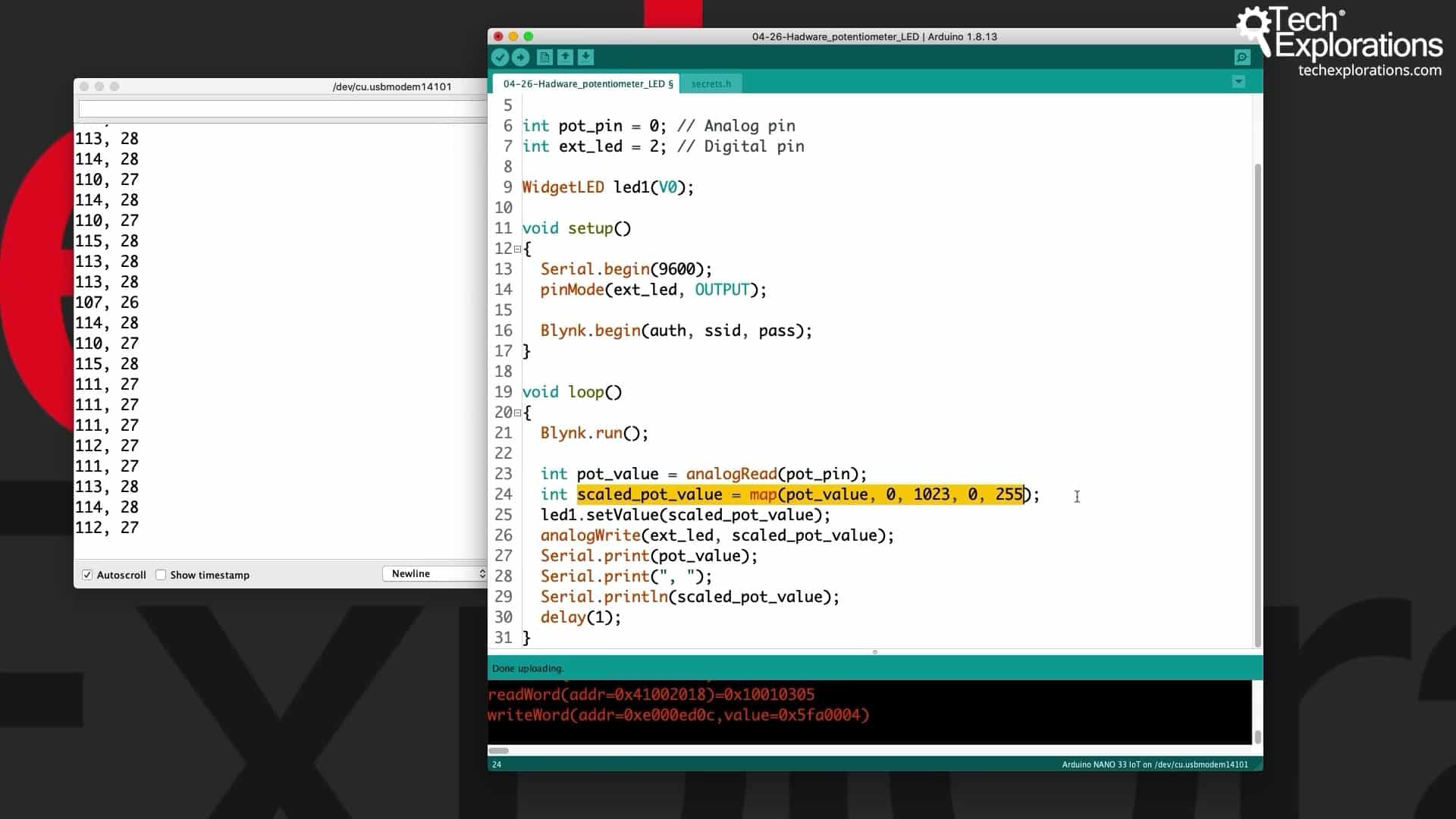
In line 24, I scale this value between 0 and 255, which is the PWM value. You can see in the documentation below that the LED widget using the set value function can accept values between 0 and 255.
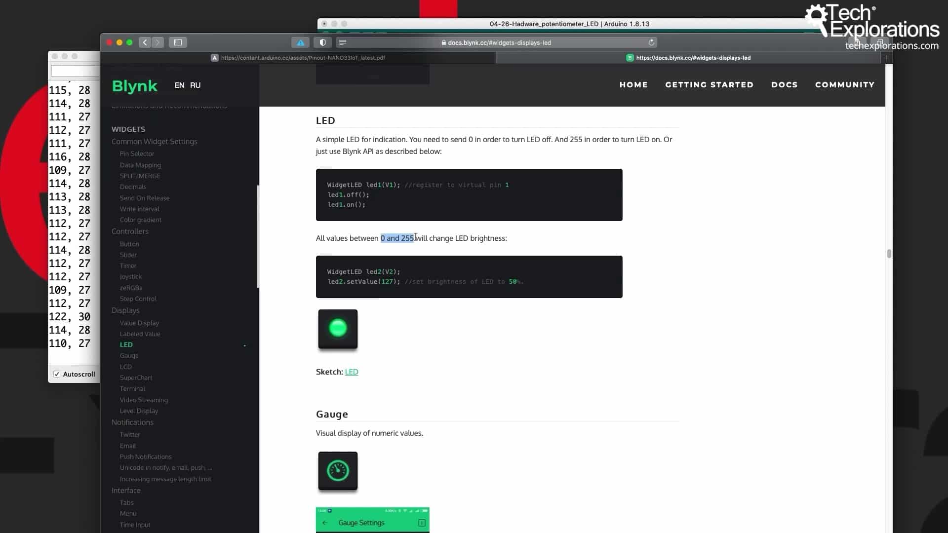
Blynk LED documentation
In this case, scaling is necessary, so that's what I will do. I get the scaled potentiometer value. In line 25, I call the set values function of the led1 object and pass that scaled value through. That will then make the simulated LED, the widget LED, light up appropriately and according to that value.
In line 26, I do the same thing, but for the hardware LED. Then, I also print the two values, the original and the scaled value, from the potentiometer to the serial monitor to see exactly what is happening.
Demonstration of the potentiometer function
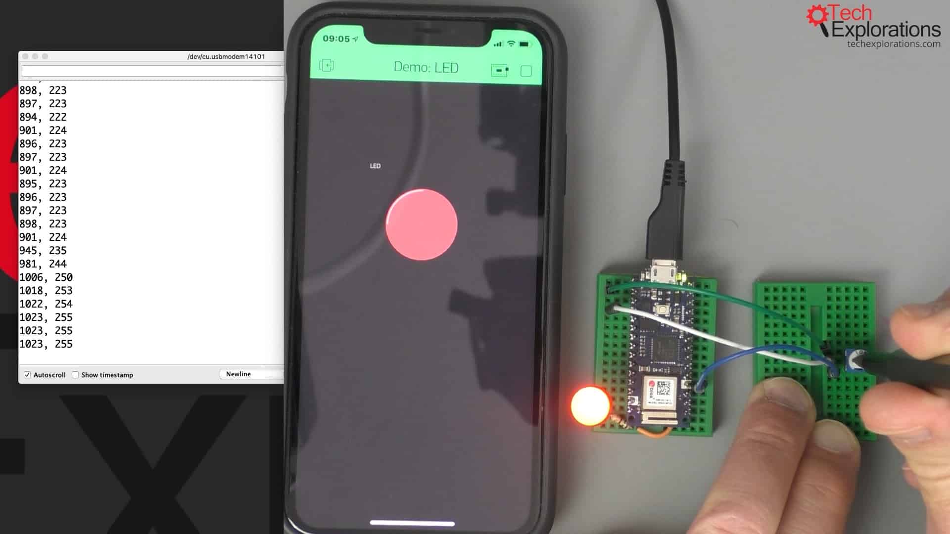
Next, I use my screwdriver and slowly turn the potentiometer toward one way, increasing values. In the two images below you can see that both LEDs, simulated and hardware, become brighter. If I go the other way, both LEDs become fainter.
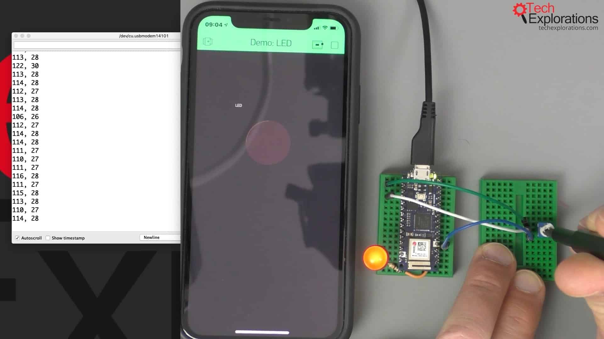
Moving the potentiometer gradually to increase the values makes the LED brighter...

...and brighter
So, the Blynk LED widget gives you a way to simulate a real-life LED inside your Blynk application.
Learn Blynk with our video course
Start right now with Arduino Mobile Development with Blynk
This is our comprehensive video course, packed with high-quality video, hands-on mini-projects, and our friendly and supporting community.
Jump to another article
1. What is Blynk?
2. Demo of a simple Blynk project
3. The Arduino Nano 33 IoT
4. Install the Blynk app, create an account
5. Create a new Blynk project
6. How to use a virtual pin
7. Replace the Arduino Nano 33 IoT with an ESP32
8. Button and styled button
9. Hardware button LED
10. Hardware potentiometer LED
11. Vertical and horizontal slider
Last Updated 3 years ago.
We publish fresh content each week. Read how-to's on Arduino, ESP32, KiCad, Node-RED, drones and more. Listen to interviews. Learn about new tech with our comprehensive reviews. Get discount offers for our courses and books. Interact with our community. One email per week, no spam; unsubscribe at any time
