Getting Started with Grove guide series
The Grove Base Shield for Arduino
In this article, I will describe the Grove Base Shield and how you can use it to connect Grove modules to your Arduino Uno (or any compatible board).
In this article, I will describe the Grove Base Shield and how you can use it to connect Grove modules to your Arduino Uno (or any compatible board).
If you prefer to watch a video, go ahead.
Purchase the Grove Base Shield for Arduino
This is a Seeed product. When you click on the red button, you will be taken to the Seeed website to complete your purchase.
This product is also part of the Grove Starter Kit for Arduino.
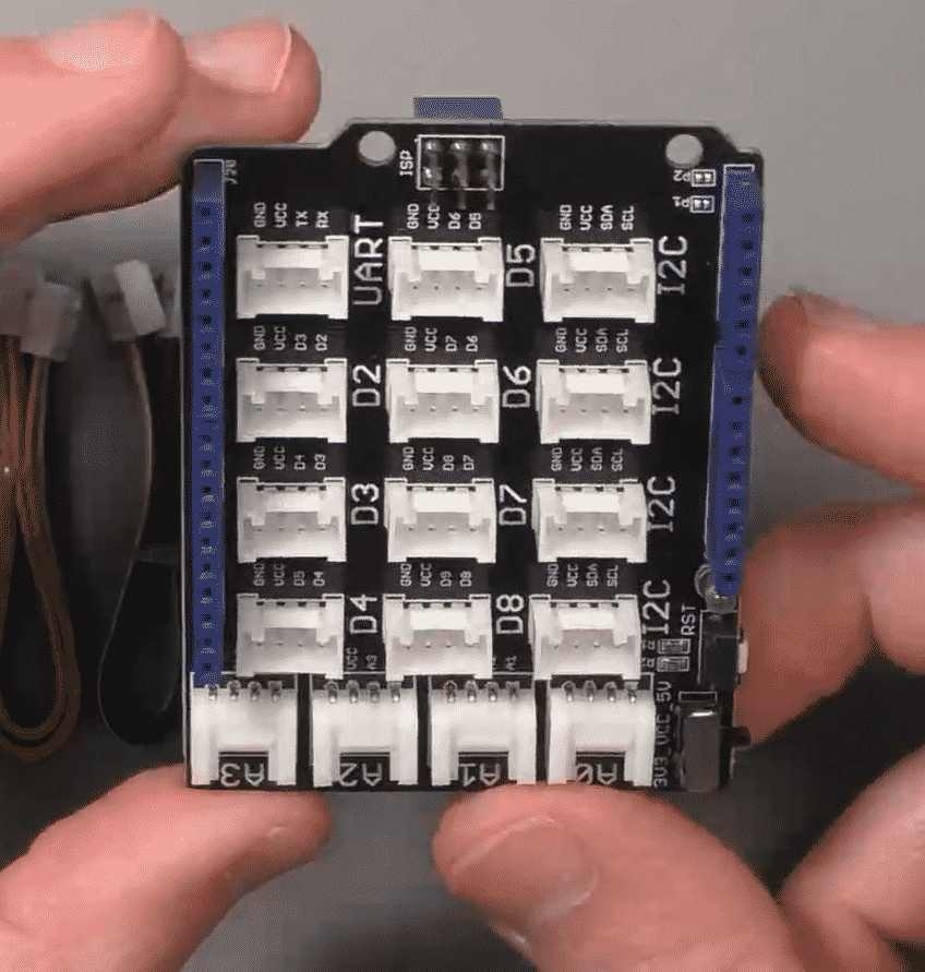
What is the Base Shield?
The Grove Base Shield is an Arduino Shield that breaks out the Arduino pins to Grove connectors. Once you plug the Base shield on the Arduino, you will be able to plug a Grove module to one of the Grove connectors on the Base Shield.
Without the Shield, you will normally use jumper wires to connect component pins to the Arduino header pins, which, as you can appreciate, is an error prone process.
Setup the Base Shield
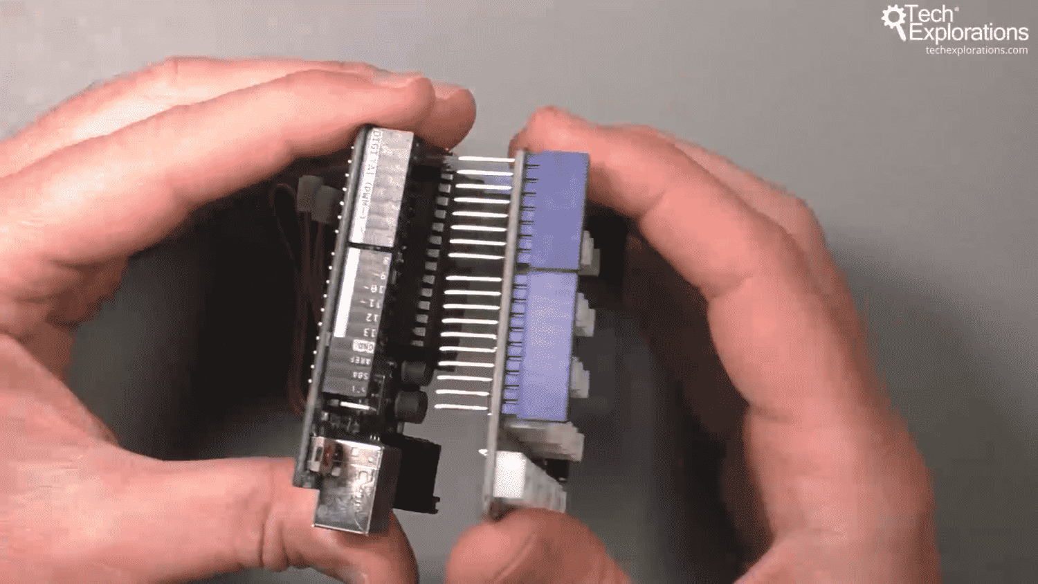
Setting up the Base Shield with your Arduino is super-easy. Just align them so that the pins of the shield match the Arduino Uno headers, and gently press the two boards together.

Attach the Base Shield on the Arduino Uno by carefully aligning the shield pins to the Arduino header and pressing.
Connect a module
To connect module, take any Grove cable, and plug it into an available Grove connector on the Base shield. The connector you should use depends on the module.
If the module is an analog device, like a potentiometer or a light sensor, use an available connector A0 to A3.
If it is a digital device, like a momentary button or an LED, use an available connector D2 to 8.
If it is an I2C device, like the RGB LCD screen that comes with the Grove Kit, use any of the I2C connectors.
And finally, if it is a UART device, use the connector marked "UART".
In this example, I want to connect an LED to my Arduino, so I will use a digital Grove connector for this purpose. Any available digital connector will do, and in the photo below you can see that I chose D2.
Try to plug the cable in the connector. Because of the geometry of the connector, you can only connect it the right way. This feature alone ensures that you will never suffer from a short circuit again!
Simple!
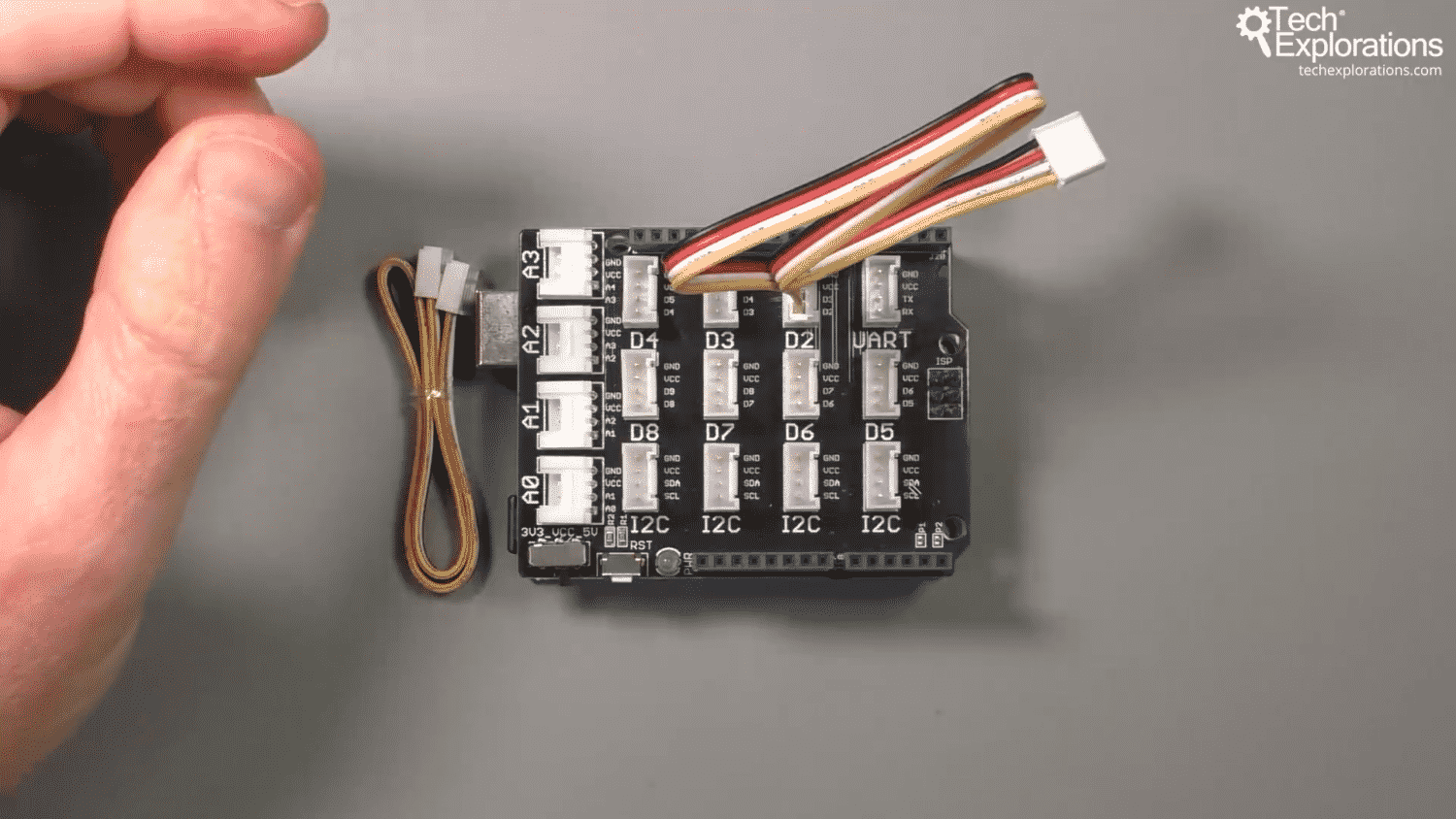
Connect a Grove cable to a Grove connector on the Base Shield. I'll be connecting an LED module, so in this example I have used connector D2.
Let's move to the Grove component. In this example, I want to connect an LED module. Take the LED module from the kit, and plug in a 5mm LED (also available in the kit). Beware of the polarity of the LED. The long pin (anode) should go in the LED module socket marked "+".
Then, take the free end of the Grove cable you just plugged into the Base Shield, and plug it in the LED module.
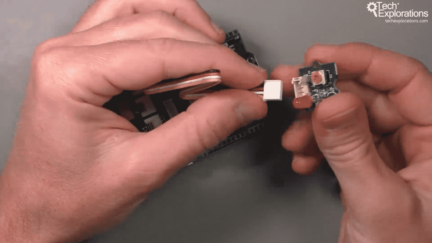
Connect the other end of the Grove cable to the LED module.
That's it! Your LED module is connected to the Arduino. We can go on to the Arduino IDE to write the sketch that drives the LED. But first, let's have a look at the difference between an Arduino Pin number and a Grove connector number.
Pin numbers and connector numbers
You are probably familiar with Arduino pin numbers. Those numbers correspond to the pins that are exposed for our use via the Arduino headers. Because we have plugged the Grove Base Shield on the Arduino, we don't have direct access to the Arduino pins. Instead, we can access Arduino pins through the Grove connectors.
But here's the catch: We still need to know which Arduino pin we are using, via a Grove connector, so that we can use this information in the Arduino sketch.
Figuring out which Arduino pin your Grove module is using is easy. Have a look at the photo below:
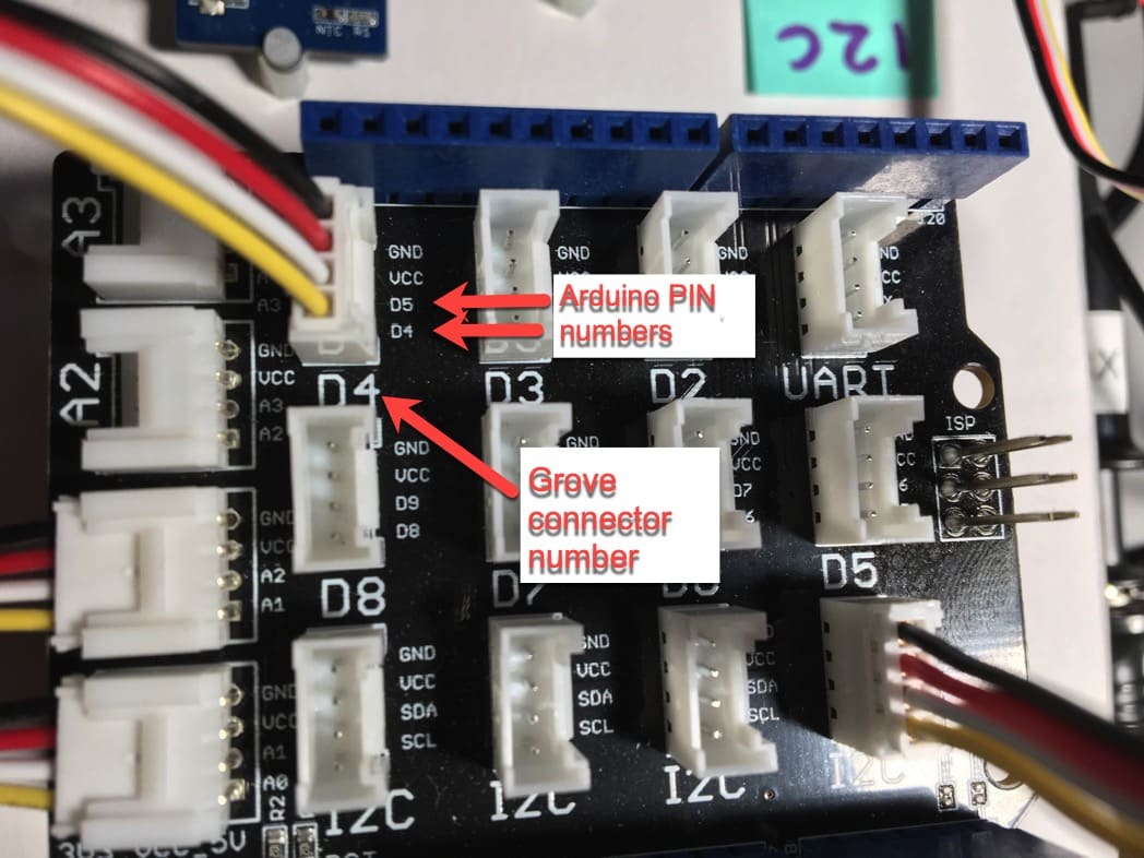
On the base shield, you can see the connector numbers in large letters: D4, D3, I2C, A2, etc. In the example in the photograph, I have connected a Grove cable to Grove connector D4.
Now, look more closely to the Grove connector D4. Notice the two arrows that point to text D5 and D4? These are the Arduino pins to which the white (D5) and yellow (D4) connect.
On a Grove module, next to its connector, you will see similar text. See an example below, of the LED module.
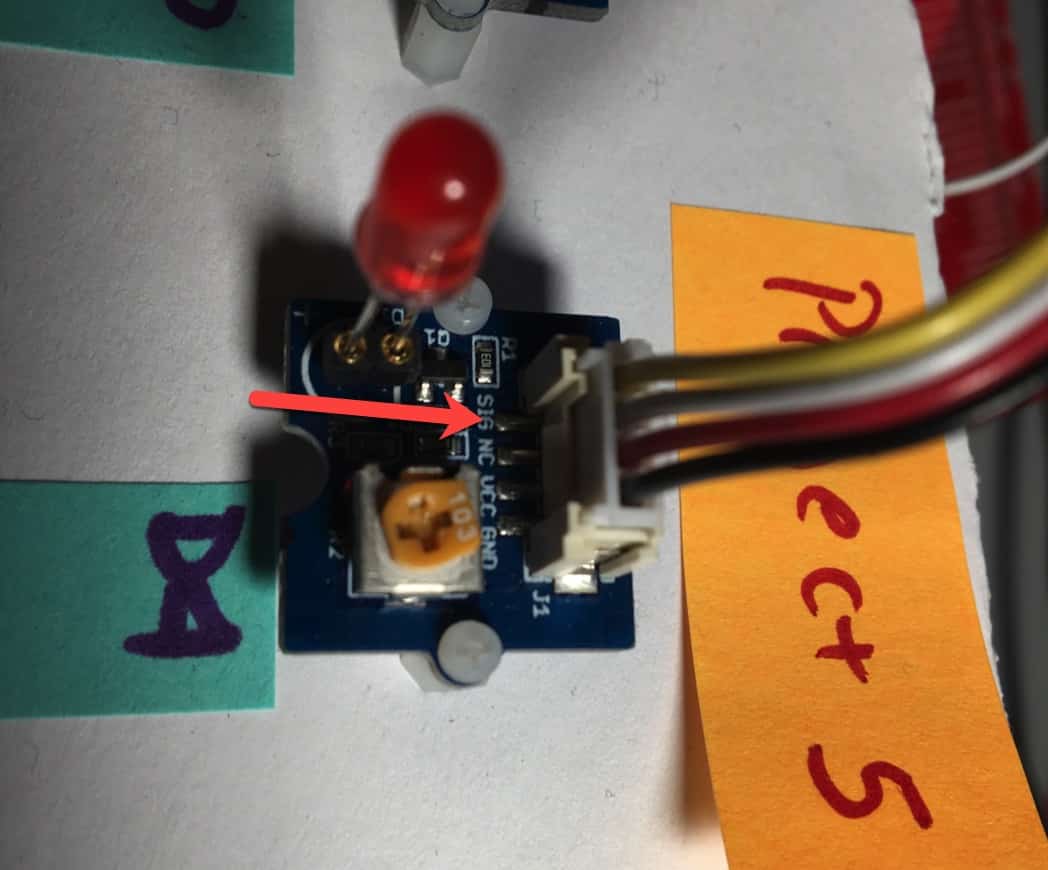
The arrow points to the yellow wire, marked "sig". This is the signal wire. Next to it is the white wire, marked "NC", or "Not connected".
Every Grove module has a Grove connector with markings the describe the role of each pin. In this example, the yellow wire conveys the signal ("SIG"). The black wire conveys GND, and the red wire conveys VCC (5 Volts).
The white wire conveys no signal, and is marked with "NC".
To work out which Arduino pins drives the LED, follow the yellow wire from the module to the Base Shield, and you will see that the Arduino pin that will do this work is D4.
With this information, you can use digital pin 5 in your Arduino sketch.
I will show you exactly how to do this in a later article in this series, were we'll experiment with the LED module and run a sketch that drives it.
In the next article, I will show you the Seeeduino, which is an Arduino Uno compatible board with integrated Grove connectors.
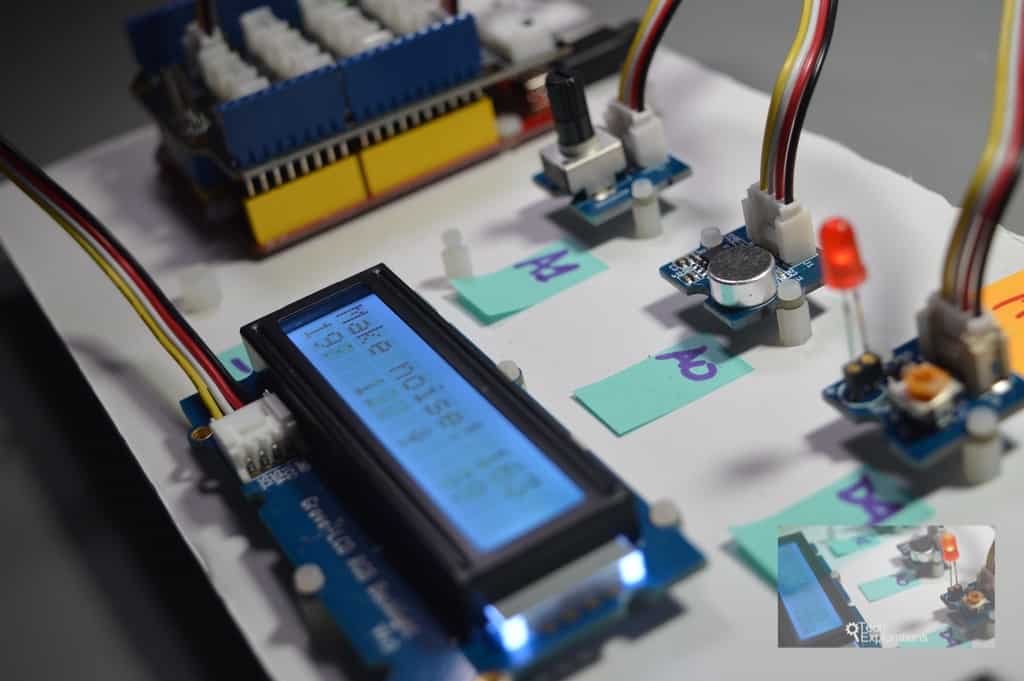
Ready for some serious learning?
Enrol to
Grove For Busy People
In this course, I’m going to show you how to use the Grove system for the Arduino.
It is a course for people who know the basics of the Arduino. If you have never used an Arduino before, consider enrolling to Arduino Step by Step Getting Started first.
Just click on the big red button to learn more.
Last Updated 2 years ago.
We publish fresh content each week. Read how-to's on Arduino, ESP32, KiCad, Node-RED, drones and more. Listen to interviews. Learn about new tech with our comprehensive reviews. Get discount offers for our courses and books. Interact with our community. One email per week, no spam; unsubscribe at any time
