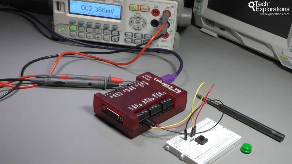
In this lesson, I'll demonstrate how to use a momentary button with one of the analog inputs on the LabJack T4.
This is a simple experiment, and it give us the opportunity to have a look at how the analog input value shows up in the dashboard and also in the register matrix.
Let's begin with the wiring.
I removed the cap of the button so you can see the connections easier.
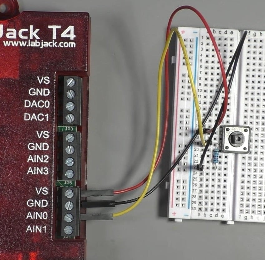
Connect the top left pin to the LabJack VS port with a red jumper wire. The VS pin provides 5V to whatever analog device I connect to my circuit.
Connect a 10KOhm resistor to the bottom left pin. and the other end to the GND port of the LabJack via a black jumper wire.
Note: It is not necessary to use an external pull-down resistor as LabJack's AIN port already have one.
Finally, connect the bottom left pin of the button to the AIN0 port via the yellow jumper wire.
That's it with the wiring. Let's go over to Kipling now.
Go ahead and start Kipling. Connect to your LabJack, and select the Dashboard tab.
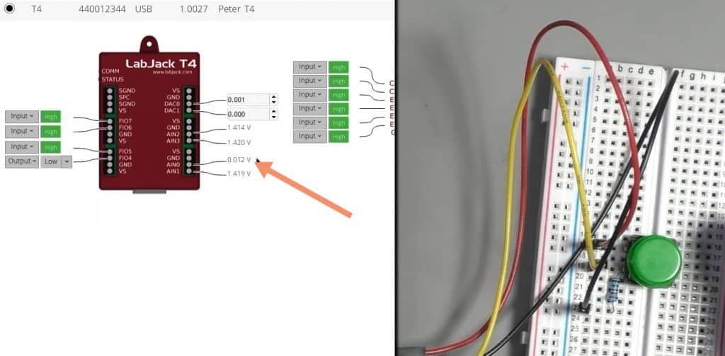
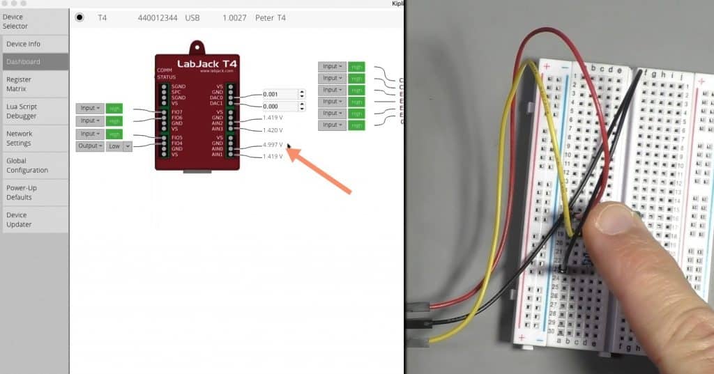
Now, observe the voltage value in AIN0.
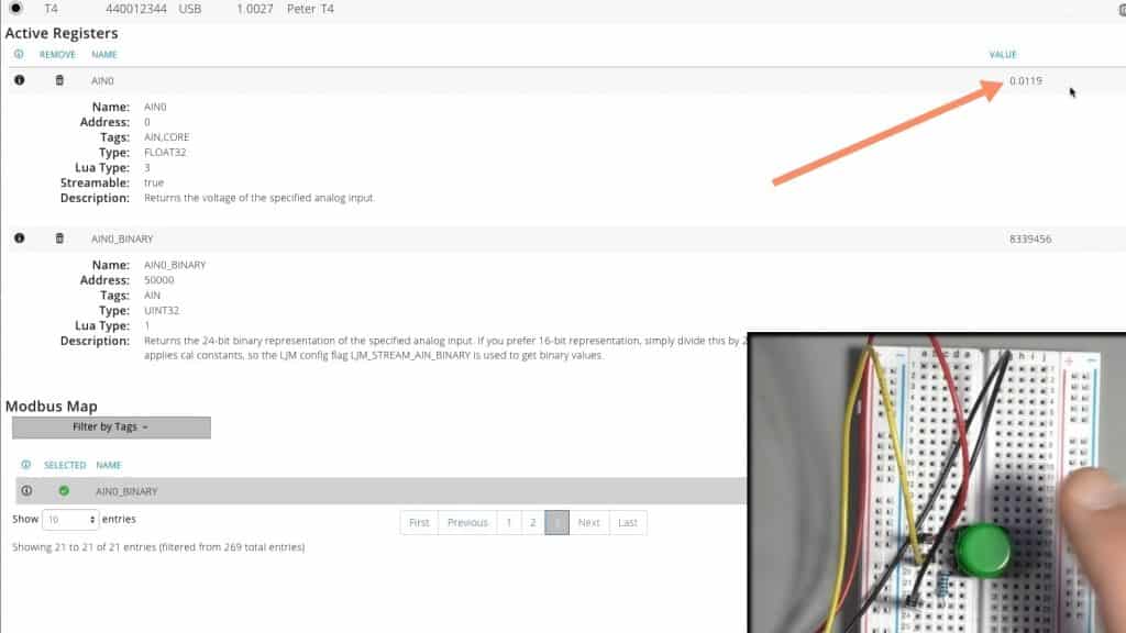
When the button is not pressed, the voltage is approximately zero volts.
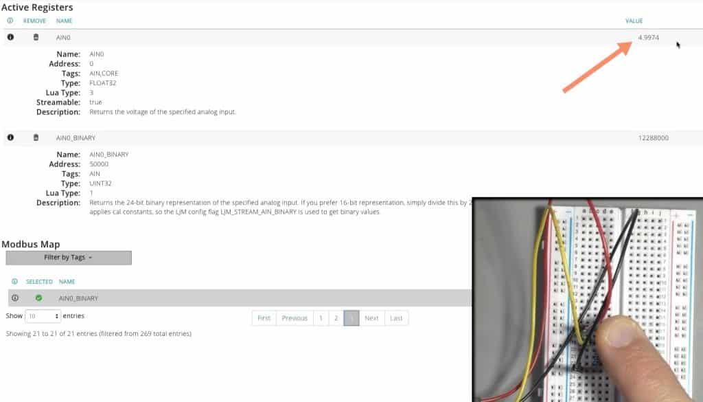
When the button is pressed the voltage becomes 4.997 volts.
Let's switch over to the Register Matrix tab, and repeat the experiment.
First, you will need to find the AIN0 register. Type "AIN0" in the search box, and then click on the tick button to select the AIN0 register that is retrieved by the search function. The register will be listed in the Active Registers list, at the top of the Register Matrix window.
Towards the right edge of the AIN0 row, you will see the register value. This is the voltage measures at AIN0.
When the button is not pressed, the value showing is almost 0V. When the button is pressed, it goes up to 4.99V. These are the values we saw in the Dashboard view.
Since we are working with the analog input (AIN) port, you can replace the button with a potentiometer, and see a variety of values measured on the port as you turn the pot knob. Let's try this experiment in the next lesson.
