Oscilloscopes For Busy People guide series
Basic functions
Let’s have a closer look at the basic functions on a digital oscilloscope.

An oscilloscope, really, does only one thing: it captures a representation of a live signal from a test circuit and displays it on a screen. Most often, this representation is the voltage of the signal as it changes over time.
Based on the information that the oscilloscope captures about the signal, modern digital oscilloscopes ofter two other important functions:
- the automatic measurement of various parameters of the signal, like its frequency, peak-to-peak voltage, duty cycle and rise time, and
- For signals that encode information, to decode that information and display it on the screen. For example, if the oscilloscope has captured the waveform that encodes serial UART information, we can set it so that this information is extracted from the waveform and displayed on the screen.
Almost all modern oscilloscopes offer these capabilities. The extend of their ability to automatically measure and decode differs between models and budgets.
Let’s have a closer look at the basic functions on a digital oscilloscope.
Plot signal waveform
The first and most important function of an oscilloscope is to display a signal, live, on its screen.
As the signal changes, the oscilloscope updates its display in close real time to reflect this change.
In this example, I’m chaining the duty cycle of a PWM signal using a potentiometer, and the oscilloscope is able to show the signal as it changes on the screen.
In this example, also notice the row of measurements below the graph. Those are also updated in real time.
Capture a waveform
Often, we want to capture or “freeze” a waveform so that we can examine it more closely. This allows us use to use tools like the cursors or enable multiple automatic measurements to look at specific parts of the waveform that is of interest.
In this small example, which comes from one of the experiments in Oscilloscopes for Busy People, I have captured a single waveform that was produced by the press of a momentary button. With the waveform captured, I can then go ahead and use the cursors to make a measurement. At the top right corner of the oscilloscope, notice the red “Run|Stop” button, indicating that what I am looking at is the waveform captured and frozen in time, not a live waveform.
Trigger control
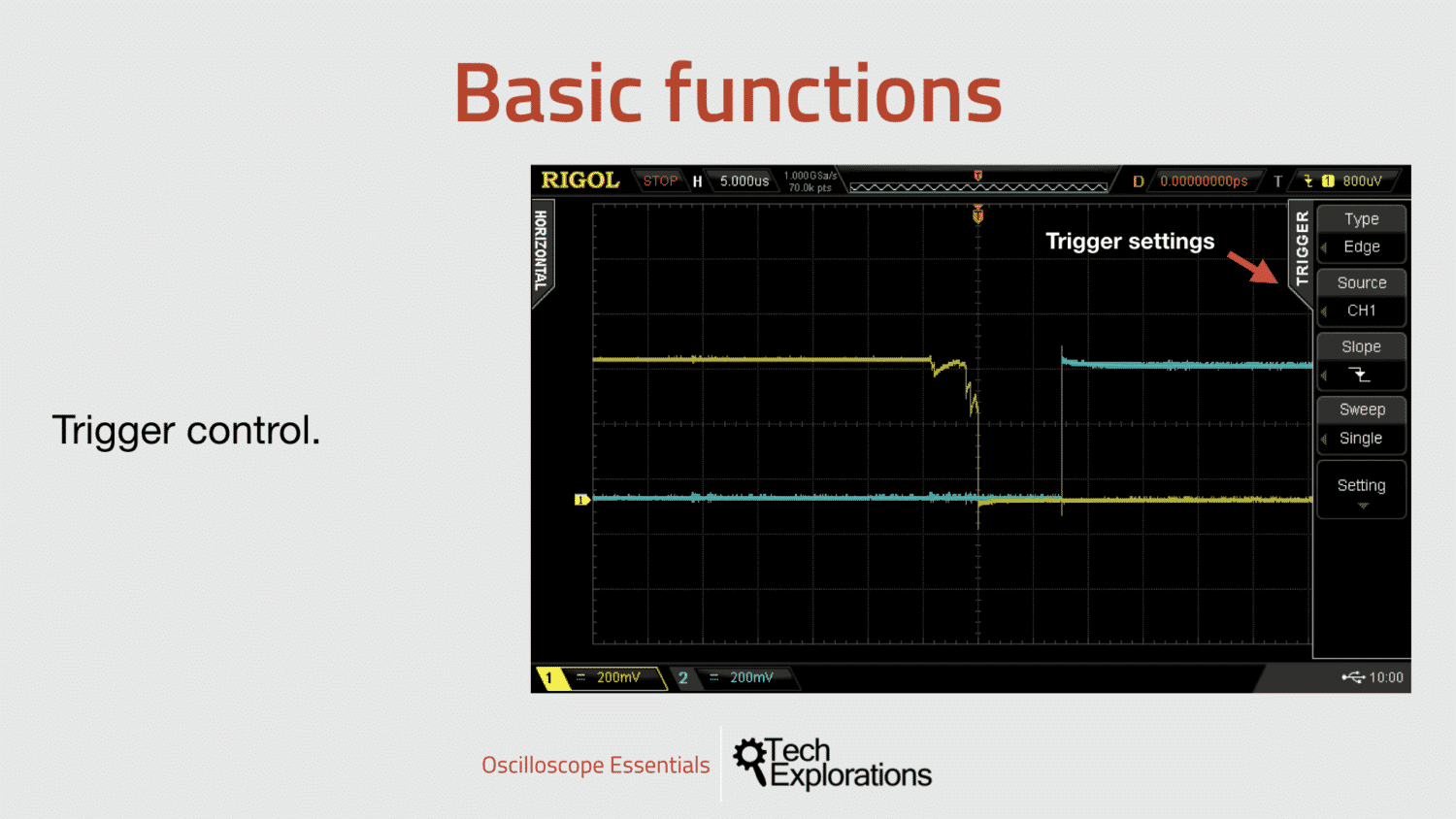
The trigger is a fundamental function of any oscilloscope. A trigger is defined by a full set of configurations that we use to prepare the oscilloscope to be able to recognise the waveform that we want to examine.
A trigger works by detecting a specific change in the signal it is monitoring, such as going from 0V to 5V within between 1 ms and 5 ms. Remember, triggering is all about change, and the type of change we expect in a signal.

A trigger works by detecting a specific change in the signal it is monitoring.
Modern oscilloscopes can detect many kinds of signals out of the box based on the changes in the voltage over time.
Most oscilloscopes have an automatic trigger function that can figure out how to capture regular, periodic signals without the user having to define its characteristics. This makes oscilloscopes user friendly so that people with no experience in using them can make simple measurements.
On top of this, oscilloscopes offer many types of signals that we can select and configure manually. In the screenshot in this example, I have set my oscilloscope to look for the most common kind of signal change, an Edge, coming from Channel 1, that goes from High to Low, and that is triggered when voltage drops below 800 microVolts (uV).
In the experiments in this course, I’ll show you how to use a variety of triggers, like Edge, RS232 and I2C.
Measurements
Modern oscilloscopes can measure multiple parameters of a live signal, and show the results of the measurements on the screen.
In Oscilloscopes for Busy People, I’ll show you many examples of measurements in each of the experiments in this course.
In this video clip, the oscilloscope is automatically measuring the frequency, period, and the maximum voltage of the waveform on the screen.
It’s doing this “live” and updates these measurements multiple times per second. You can see the results of the measurements just below the graph. The measurements include the current measured value, the average, minimum and maximum values.
Decoding
A more advanced, but common, feature of modern digital oscilloscopes is the ability to decode a signal that contains information. When two devices communication, they use a specific protocol so that data can travel between them. For example, in micro controller and microcomputer applications, common protocols are serial UART, I2C, SPI, and CAN.
The protocol describes how a value, like a number or a character, is encoded into a waveform with a specific shape.The waveform, with this shape, contains information. At the receipt end, a device reverses the translation to extract the information contained in the waveform.
Oscilloscopes with decoding capability can eavesdrop in the communication between two devices, and extract the information that is contained in the waveform, as it travels through the wire.
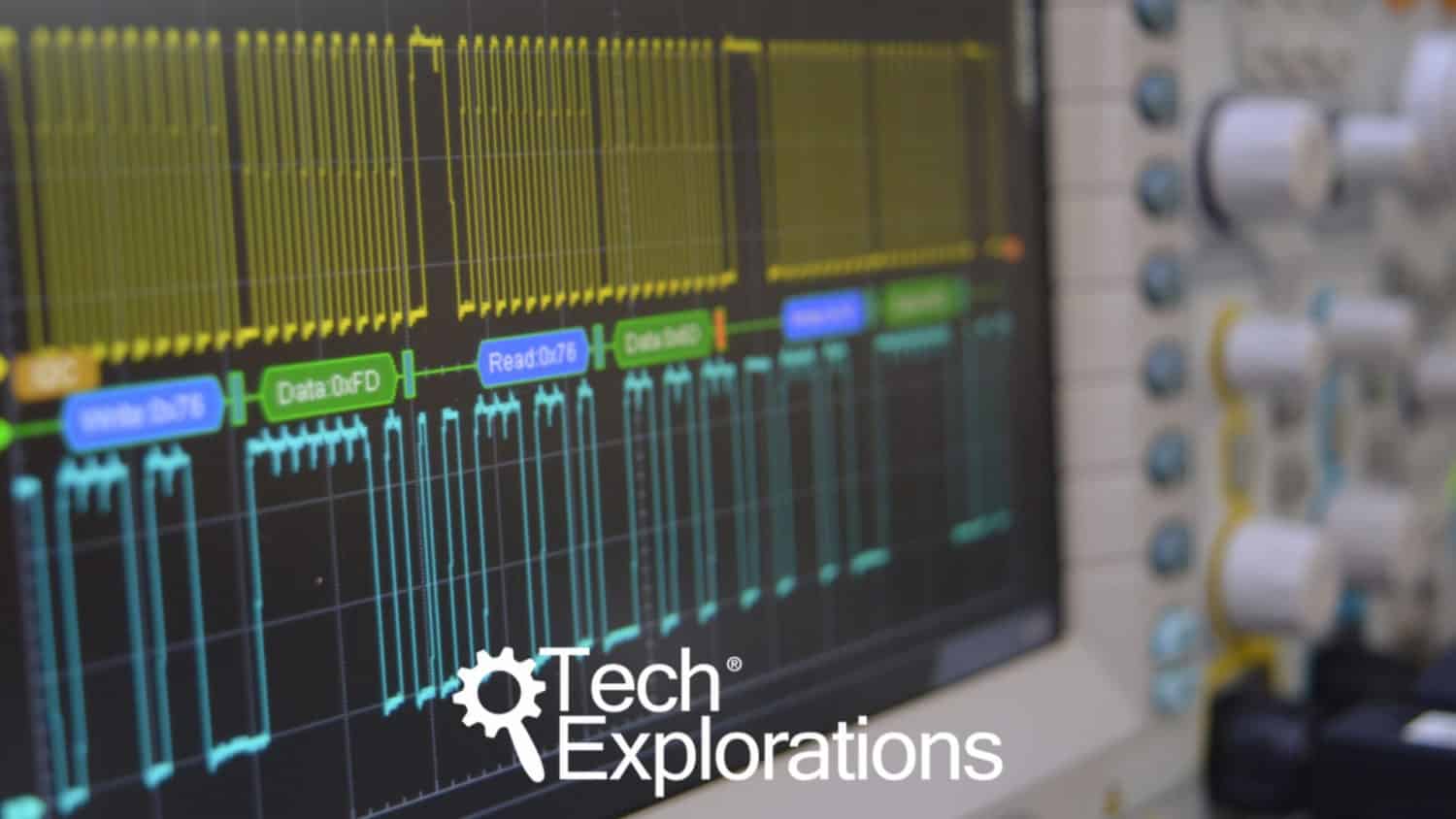
In this video clip, which I’ve taken from one of the experiments in this course, the oscilloscope is decoding serial UART communication between an Arduino and a computer.
By decoding communication between devices, you can troubleshoot problems and confirm that your hardware is working as expected.
Before I finish this lecture, I want to mention that although oscilloscopes can do decoding of signals, this is really an add-on feature. There are other instruments, called “logic analysers” that are specialised for this specific task.

Ready for some serious learning?
Enrol to
Oscilloscopes for Busy People
Demystify the oscilloscope and learn how to use it in your projects.
This course is perfect for people who have never used an oscilloscope.
Through a series of projects, this course will teach you how to use an oscilloscope to measure and decode signals in your electronics.
Just click on the big red button to learn more.
Last Updated 1 year ago.
We publish fresh content each week. Read how-to's on Arduino, ESP32, KiCad, Node-RED, drones and more. Listen to interviews. Learn about new tech with our comprehensive reviews. Get discount offers for our courses and books. Interact with our community. One email per week, no spam; unsubscribe at any time
