Motors guide series
Project 2: DC motor speed and direction control with a potentiometer
In this project, you will learn how to control the speed and direction of spin of the DC motor's rotor. You will use a potentiometer to provide input to the Arduino, and the map() and analogWrite() functions in your sketch to make this work.

In Project 1 you learned how to control two DC motors with an Arduino Uno and an L298N motor driver. In this experiment you will take the next step. You will learn how to control the speed and the direction of the two motors. In the role of the user interfaceyou will use a 10 kΩ potentiometer.
You will use the potentiometer in two ways:
- First, you will use the potentiometer to control the speed of the motors, but not the direction.
- Second, you will use the potentiometer to control both the speed and the direction o the motors.
The project 2 components
You will only need to add a 10kOhm potentiometer to the circuit of Project 1. To save you from jumping to the Project 1 page, I'm copying the full list of components here.
The new item is #6:
- Two 5V DC motors.
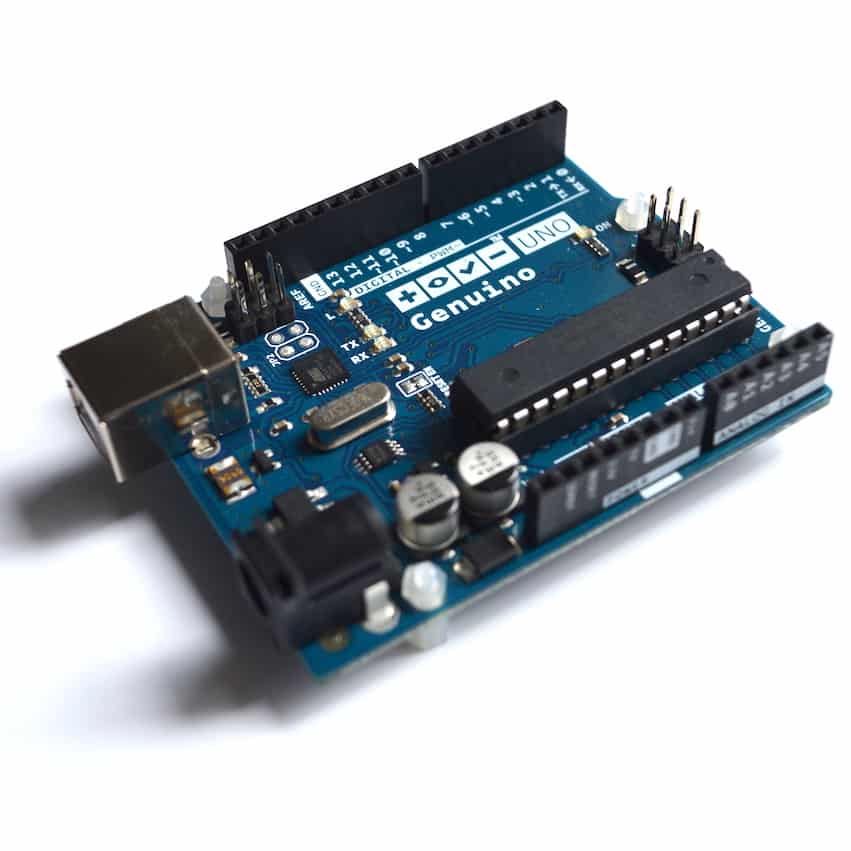
- An Arduino Uno.
- A motor controller module with the L298N chip.
- One AA-battery pack with 4 batteries.
- A bunch of jumper wires.
- A 10 kΩ potentiometer.
The project 2 circuit
Let's do the wiring. You can add the potentiometer to the circuit from Project 1. I am copying here the complete instructions so that you don't have to jump back and forth between the two articles.
The new items in the list are #10 and #11.
Start by unplugging the Arduino from your computer so that it is not in operation.
- Connect the first motor to motor controller module Out1 and Out2. The order does not matter.
- Connect the first motor to motor controller module Out3 and Out4. The order does not matter.
- Connect the positive wire from the battery pack to pin +12V on the module.
- Connect the negative wire from the battery pack to pin GND on the module.
- Connect the GND pin of the module to the GND pin of the Arduino.
- Connect Arduino pin 5 to module pin In1.
- Connect Arduino pin 4 to module pin In2.
- Connect Arduino pin 3 to module pin In3.
- Connect Arduino pin 2 to module pin In4.
- Connect the middle pin of the potentiometer to Arduino pin A0.
- Connect the other two pins of the potentiometer to Arduino pins 5V and GND.
- Inspect the wiring and ensure they are correct.
Here’s the demo 2 circuit:

The only difference to the Project 1 circuit is the addition of the rotary potentiometer. It is connected to the 5V and GND columns on the breadboard, and to analog pin 0 on the Arduino. The 9V batteries depict the motor battery power supply. The black module in the middle of the breadboard depicts the L298N motor driver module with the connections as described earlier.
Sketch for Project 2, version 1: Control speed with a potentiometer
Here’s the first sketch for Project 2. This sketch allows the control of only the rotational speed of the two motors:
int E1 = 5;
int M1 = 4;
int E2 = 6;
int M2 = 7;
void setup()
{
Serial.begin (9600);
pinMode(M1, OUTPUT);
pinMode(M2, OUTPUT);
}
void loop()
{
int potentiometerVal = analogRead(A0);
Serial.println(potentiometerVal);
move_motors(potentiometerVal);
}
void move_motors(int potValue)
{
int mappedVal = map(potValue,0,1023,0,255);
digitalWrite(M1,HIGH);
digitalWrite(M2, HIGH);
analogWrite(E1, mappedVal); //PWM Speed Control
analogWrite(E2, mappedVal); //PWM Speed Control
delay(30);
}
I have highlighted the changes and additions from the sketch in Project 1 in red.
In the loop() function, we take a reading from analog pin 0 where the middle pin of the potentiometer is connected. We then call the function move_motors and pass the potentiometer reading to it.
Inside the move_motors() function, we map the potentiometer reading (which comes in the range of 0 to 1023) to a value between 0 and 255 (which is the range of valid values for the PWM pins), set the direction of rotation for the two motors using the digitalWrite functions, and set the speed using the PWM function analogWrite() to be mappedVal (which in turn is relevant to the value we set by turning the potentiometer).
Upload this sketch and turn the knob of the potentiometer back and forth. See how the speed of the motors change accordingly?
Sketch for Project 2, version 2: control speed and direction with a potentiometer
There’s one more thing to do, and that is to also be able to control the direction of rotation of the motors, not just the speed. What I’d like to do is to be able to accelerate the motor towards one direction when I turn the knob of the potentiometer towards the left, and to the opposite direction when I turn the knob towards the right.

Schematically, this is what I would like to achieve: The red circle represents the potentiometer knob, and the black shows movement of the knob towards the left or the right.
Motors move anti-clockwise
Neutral - motors don’t move
Motors move clockwise
We are only going to make an adjustment to the sketch to make this happen, no need to modify the circuit at all.
Here is the modified sketch:
//Arduino PWM Speed Control:
int E1 = 5;
int M1 = 4;
int E2 = 6;
int M2 = 7;
void setup()
{
Serial.begin (9600);
pinMode(M1, OUTPUT);
pinMode(M2, OUTPUT);
}
void loop()
{
int potentiometerVal = analogRead(A0);
Serial.println(potentiometerVal);
move_motors(potentiometerVal);
}
void move_motors(int potValue)
{
if (potValue < 512)
{
int mappedVal = map(potValue,0,512,0,255);
//Going forward
digitalWrite(M1,HIGH);
digitalWrite(M2, HIGH);
analogWrite(E1, mappedVal); //PWM Speed Control
analogWrite(E2, mappedVal); //PWM Speed Control
delay(30);
} else
{
//Going backward
int mappedVal = map(potValue-512,0,512,0,255);
digitalWrite(M1,LOW);
digitalWrite(M2, LOW);
analogWrite(E1, mappedVal); //PWM Speed Control
analogWrite(E2, mappedVal); //PWM Speed Control
delay(30);
}
}
I have highlighted in red the part of the sketch that has changed from the script in demo 2.
In the move_motors(int pot_value) function, potValue, the value read from analog pin 0 where the potentiometer is connected, is tested using the if function. If potValue is less than 512, then the first block is executed, if not then the second block is executed.
In block 1 and 2, the motor control functionality from demo 2 is repeated with the difference that now we now need to recognize that the potentiometer’s range of output values is divided to two parts. The first part, from 0 to 512, is used for moving the motors towards one direction, while the second one, 513 to 1023, moves the motors towards the other direction.
The only other difference between these two blocks is that in Block 1, a HIGH is written to M1 and M2, while in Block 2 we write a LOW, therefore spinning the motors towards the opposite direction.
Go ahead, try it.
If you are having any difficulty understanding what is going on in Blocks 1 and 2, experiment with the sketch. Try changing the map function values to something different.
For example, in Block 2, instead of
map(potValue-512,0,512,0,255)
try
map(potValue,0,512,0,255)
and upload the sketch.
What happens to the rotational speed of the motors?
Perhaps you could try this too:
map(potValue,512,1023,0,255).
Upload and compare to the previous two versions.
Can you notice any difference in behavior?
Can you explain any differences or similarities?
Learn more
If you would like to learn how to use DC motors with your Arduino, consider enrolling to Arduino Step by Step Getting Serious.
We have a full section (Section 16) with 10 lectures dedicated to this topic.
New to the Arduino?
Arduino Step by Step Getting Started is our most popular course for beginners.
This course is packed with high-quality video, mini-projects, and everything you need to learn Arduino from the ground up. We'll help you get started and at every step with top-notch instruction and our super-helpful course discussion space.
Jump to another article
2. How to drive a DC motor without a motor driver module
3. What is "microstepping"?
4. Direct current motor
5. Project 1: Control two DC motors with your Arduino and the L298N controller
6. Project 2: Control speed and direction with a potentiometer
7. Project 3: DC motor control with a distance sensor
8. Project 1: Control a servo motor with a potentiometer
9. Project 2: Servo motor control with VarSpeedServo

Done with the basics? Looking for more advanced topics?
Arduino Step by Step Getting Serious is our comprehensive Arduino course for people ready to go to the next level.
Learn about Wi-Fi, BLE and radio, motors (servo, DC and stepper motors with various controllers), LCD, OLED and TFT screens with buttons and touch interfaces, control large loads like relays and lights, and much much MUCH more.
Last Updated 2 years ago.
We publish fresh content each week. Read how-to's on Arduino, ESP32, KiCad, Node-RED, drones and more. Listen to interviews. Learn about new tech with our comprehensive reviews. Get discount offers for our courses and books. Interact with our community. One email per week, no spam; unsubscribe at any time

