Motors guide series
How to drive a DC motor without a motor driver module
DC motors draw currents that can be beyond the ability of the Arduino to supply. Transistors can be used as very simple at fast on/off switches and are an excellent option for designing simple motor controllers.
Any DC motor can be driven with PWM simple signals that can be generated by the Arduino Uno and virtually any other microcontroller. Just like you can control the intensity of an LED, you can use PWM to control the rotational speed of a DC motor.
Whether it is a miniature 3V motor for toys, or a large 12V or 24V motor for your lawnmower, the principle of operation is the same.
DC motors and current requirements
The amount of current that a DC motor requires depends on the size of the motor. How large it is, the length of the wire in the motor coils, and the load that is attached to the motor. Because the Arduino Uno can only supply a few tens of milliamps (20mA, to be exact) of current through its digital pins, you should assume that it will not be able to safely power even the smallest DC motor.
A motor draws the most current when its rotor is stationary. This is true when it starts, or when it is unable to move the attached load.
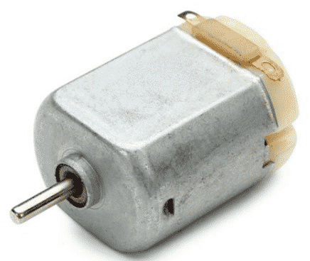
A 3V to 5V DC motor used in hobby applications.
Things get worse for larger motors. A 12V DC motor with nominal resistance in its coil of 15Ω will draw around 0.8A of current when it's starting its rotation. That's way too much, and it can damage destroy your Arduino.
For example, a tiny 3V DC motor with a 15Ω total resistance in its coil (like the one in the photo above) will draw 0.2A of current.
This is just within the Arduino's I/O pin current limit. However, but if your motor's resistance is slightly smaller, the current can easily increase more than the 0.4A which exceeds the Arduino's safe operating limits. If this happens, your Arduino will be damaged.
DC motor driver hardware
This is why we use specialized motor driver hardware to power and control the motor.
The L298N motor driver is easy to use and cheap, with a peak current capability of 3A. This amount of current is sufficient for more regular applications, like controlling a small fan or a robot.
A transistor as a simple DC motor controller
If you are looking for the simplest possible way to control a DC motor, then you will need a single transistor. You can choose a transistor that is appropriate for the current requirements of the motor that you want to control.
A Darlington
TIP122
transistor is a common device used in DC motor control applications.
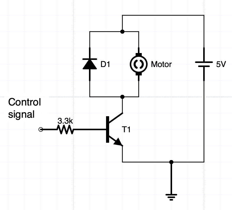
A Dalrington transistor used to control a DC motor.
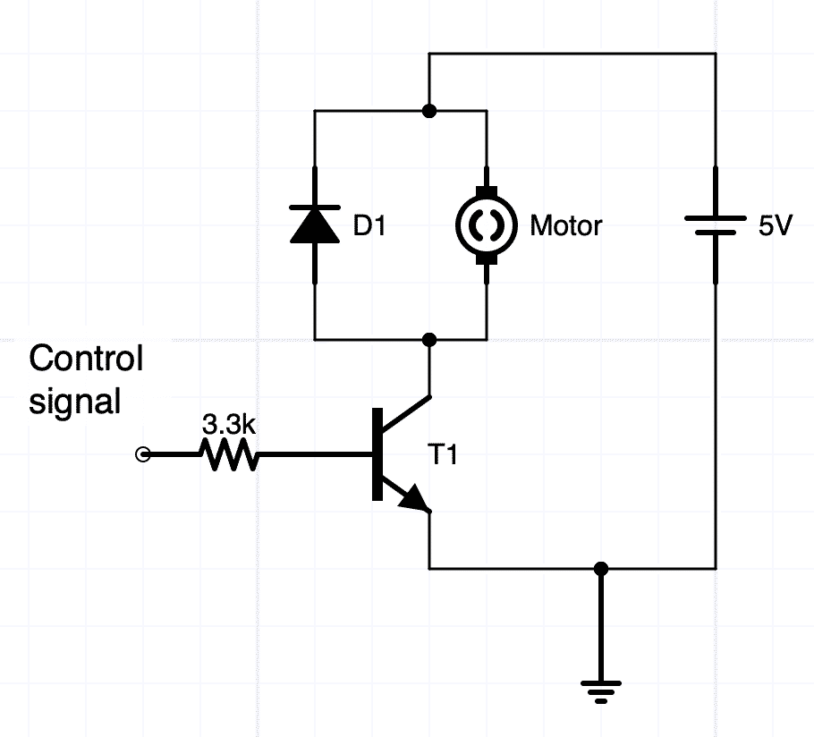
The Darlington TIP122 can provide 5A of continuous current through its collector and 15A of peak current, which can be drawn when a large motor starts. You can see it marked as "T1" in the schematic above.
Your Arduino can easily control the transistor, since it only needs 2.5V in its base to switch on (notice the label "Control signal" on the left of the current limiting resistor in the schematic above).
You can add a resistor (~3.3kΩ) to protect the Arduino across the base of the transistor, and a diode (like the 1N4004) to block back-currents from the motor, and you have your motor driver, capable of regulating the rotational speed using PWM. If your motor is brushed, also add a small capacitor (~1uF) across the terminals of the motor to help with the electrical noise.
The power that drives the motor can come from an external power supply or a large batter. For example, you can drive a 12V motor from a mains (walled) 12V power supply that you recycle from an old appliance. In the example schematic, I am using a 5V power source for the motor.
In your Arduino sketch, you can use a simple PWM sketch like this:
int motor = 9;
int speed = 0;
int speedAmount = 5;

void setup() {
  pinMode(motor, OUTPUT);
	}

void loop() {
  analogWrite(motor, speed);
	speed = speed + speedAmount;
	if (speed <= 0 || speed >= 255) {
	  speedAmount = -speedAmount;
	}
	delay(30);
}
According to the sketch, the base of the transistor, via the resistor, is connected to Arduino's pin 9. In setup(), we configure the pin to be an output. In the loop(), we use analogWrite() to get the motor to gradually increase its rotational speed, and then to gradually decrease it.
Learn more
An excellent discussion of the use of discreet transistors to control a DC motor with schematics is here.
If you would like to learn how to use DC motors with the Arduino, consider enrolling to Arduino Step by Step Getting Serious.
We cover stepper motors in a dedicated section (Section 16) that contains 10 lectures.
New to the Arduino?
Arduino Step by Step Getting Started is our most popular course for beginners.
This course is packed with high-quality video, mini-projects, and everything you need to learn Arduino from the ground up. We'll help you get started and at every step with top-notch instruction and our super-helpful course discussion space.
Jump to another article
2. How to drive a DC motor without a motor driver module
3. What is "microstepping"?
4. Direct current motor
5. Project 1: Control two DC motors with your Arduino and the L298N controller
6. Project 2: Control speed and direction with a potentiometer
7. Project 3: DC motor control with a distance sensor
8. Project 1: Control a servo motor with a potentiometer
9. Project 2: Servo motor control with VarSpeedServo
Done with the basics? Looking for more advanced topics?
Arduino Step by Step Getting Serious is our comprehensive Arduino course for people ready to go to the next level.
Learn about Wi-Fi, BLE and radio, motors (servo, DC and stepper motors with various controllers), LCD, OLED and TFT screens with buttons and touch interfaces, control large loads like relays and lights, and much much MUCH more.
Last Updated 1 year ago.
We publish fresh content each week. Read how-to's on Arduino, ESP32, KiCad, Node-RED, drones and more. Listen to interviews. Learn about new tech with our comprehensive reviews. Get discount offers for our courses and books. Interact with our community. One email per week, no spam; unsubscribe at any time

