In many cases, knowing the exact force and direction applied to our gadgets is an overkill; just knowing that a bottle has been tipped over is enough to know that the lid should close automatically.
For simple cases like that, a 3-axis accelerometer is an overkill. We could use a simple sensor that can detect the shock of an impact or for being upside down.
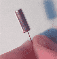
The tilt and impact sensor is a simple switch which closes a circuit when positioned in a particular way. They are very cheap, around $5 on eBay for a pack of 10. They come in a variety of shapes, but usually they are made of a tiny metallic cylinder with a thin copper wire coming out of one end.
The cylinder contains wires or a metal ball. When the device is hit or when its orientation changes, the wires or the ball come in contact with the wall of the cylinder and closes a circuit between the cylinder and the external wire.
They can be very sensitive, so care must be given to compensating for this sensitivity, otherwise we would be getting readings that look chaotic. We are going to ignore this sensitivity for now.
Here is what a tilt sensor looks like from the outside…
To put this circuit together, we'll just use the Arduino, no breadboard is required.
We need to do a bit of soldering in order to connect the sensor to wires which we can connect to the Arduino. If you have never done soldering before, follow this tutorial for some instructions. Be careful not to get burned!
Here's what we are going to build.
This is another very simple sketch. We'll just use the analog pin to determine if the switch inside the sensor is closed or open. You could just as easily have used a digital pin since there are only two states to detect, open or close, which nicely translate to HIGH or LOW.
Here is the sketch on Github.
Try out by connecting the sensor to the Arduino and moving the sensor in different directions. This is easier if you use some electrical tape to keep the sensor wires tidy. You could even stick the sensor onto the Arduino, and move the whole assembly instead of only the sensor. This will help in keeping the connections firm.


