Arduino Sensors & Actuators guide series
Measuring light
Measuring light with the Arduino is really easy. There are many sensors capable of detecting or measuring light, but the photo-resistor is one of the easiest to use.
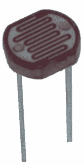
Measuring light with the Arduino is really easy. There are many sensors capable of detecting or measuring light, but the photo-resistor is one of the easiest to use. A photo-resistor is simply a resistor in which the resistance changes in accordance to its exposure to light.
The photo-resistor
You can find these devices on eBay for less than $3 for a pack of ten. Think about what you can do with a device that can detect light. Of course, your gadget will be able to know if its day or night, or if the lights are on. So you could build a gadget that turns on a small light at the entrance of you home when it darkens, so you don't have to walk in the dark.

You could also use a photo-sensitive device to allow two gadgets to communicate with light; this is the principle behind the typical television remote control where the remote control and the television communicate using infrared light. You could also build a simple robot that follows a bright or dark line on the floor. Can you think of anything else you could do with a light sensor?
Create a light-sensing circuit
We'll now create a circuit that contains a photo-resistor, and we'll use an Arduino sketch to take light intensity readings from it.
Look at the circuit in the image below, and try to copy it. Here are a few things to be extra careful about:
- Counting from the right, the photo-resistor is connected to a socket in column 1. Its second leg is connected to a socket in column 4.
- We use a 1 kOhm resistor (or close, the exact rating is not important in this exercise) in series with the photo-resistor in order to create a "voltage divider". More about this in a minute.
- Connect the resistor's second leg to a socket in column 8.
- Connect the black jumper wire to the GND socket on the Arduino, and the red to 5V. Even if you switch these connections, this circuit would still work because we are not using any polarized components.
- Lastly, connect a green jumper wire from a socket in column 4 to A0, which is the Arduino analog port 0.
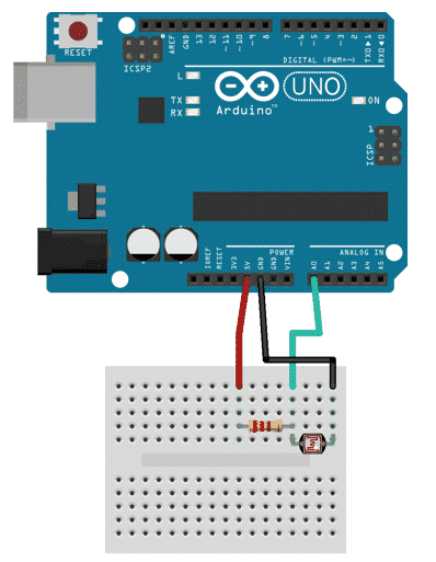
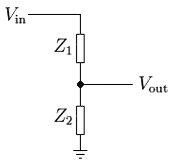
Notice how you connected the green cable in column 4, where the resistor and the photo-resistor meet? This type of wiring is called a "voltage divider" or "impedance divider", and its purpose is to create an output voltage that is a fraction of the input voltage to the divider. Look at the diagram (below):
Want to learn electronics?
Our course "Basic Electronics for Arduino Makers" is designed specifically for people that use the Arduino as a learning and creativity tool.
This course will teach you the basics of electronics so that you know what things like current limiting resistors, voltage dividers, power supplies, transistor switches, Ohm's Law, and lots more, actually are.
Vin is represented by the red jumper wire in our Arduino diagram, the earth symbol is represented by the black jumper wire. The Vout is represented by the green jumper wire. Vout depends on the impedance (resistance) of Z1 and Z2, which in the case of our Arduino circuit are the resistor and the photo-resistor. Since the resistor's resistance is fixed, and the resistance of the photo-resistor varies depending on the ambient light situation, Vout will also vary. By taking a measurement of Vout, we gain information about the light intensity in our lab.
The higher the measurement in socket A0, the more intense the light is. The closer to zero it gets, the darker our lab is.
That's enough for now with the hardware. Let's look at the software.
Sketch
Here's our program for this exercise (here is the sketch on Github):
// the setup function runs once when you press reset:
void setup() {
        // initialize serial communication at 9600 bits per second:
        Serial.begin(9600);
}
// the loop routine runs over and over again forever:
void loop() {
        // read the input on analog pin 0:
        int sensorValue = analogRead(A0);
        // print out the value you read:
        Serial.println(sensorValue);
        delay(10);
}
Much of this sketch should be familiar to you now. There's setup(), loop(), and delay(), which we have seen before.
There's a couple of new things here. First, look in the setup() function. There is this statement:
Serial.begin(9600);
This creates a serial connection which the Arduino can use to send text output to our terminal. This way the Arduino can "talk" to us. This terminal can be opened by clicking on Tools > Serial Monitor, and it looks like this:
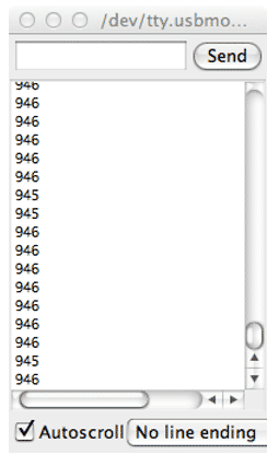
We will be printing the light intensity value to the serial monitor in a moment.
Next, have a look in the loop() function. In the first actual statement after the comment, we use the analogRead(A0) function to get a reading from socket A0 ("Analog 0") and store it to the local integer variable sensorValue. Easy, right?
We now have a value captured from the photo-resistor's voltage divider circuit, let's print it to the monitor so we can actually see it. Also easy, just do this:
Serial.println(sensorValue);
This statement, says: "Go to the serial port, print line with content 'sensorValue'". The "ln" part of the println() function means that this particular function will create a new line after it prints out the text that is contained within the parentheses. You could use just Serial.print(sensorValue), but then the output would look like this:
9469459469459459469459469469469459469
... not very useful, very hard to read.
When you send this program to the Arduino, wait for it to upload, and then open up the monitor. You will see something like this:
946
946
946
946
946
946
946
946
946
The actual values will vary because of the differences in the components you used in your circuit compared to mine, and of course the lighting conditions in our two labs are probably different. But as long as you see similar values (above 0 and below 1024), then it worked!
Ready for some serious Arduino learning?
Start right now with Arduino Step by Step Getting Started
This is our most popular Arduino course, packed with high-quality video, mini-projects, and everything you need to learn Arduino from the ground up.
Jump to another article
1: Introduction
2: How to make an LED blink
3: How to make an LED fade
4: How to use a button
5: How to use a potentiometer
6: Infrared line sensor
7: Measuring light
8: Detect tilt and impact
9: Measuring acceleration
10: Detect motion with the ultrasonic sensor
11: Detect motion with PIR sensor
12: Temperature and barometric sensor BME280
13: Measuring Temperature And Humidity
Last Updated 2 years ago.
We publish fresh content each week. Read how-to's on Arduino, ESP32, KiCad, Node-RED, drones and more. Listen to interviews. Learn about new tech with our comprehensive reviews. Get discount offers for our courses and books. Interact with our community. One email per week, no spam; unsubscribe at any time

